
Defeature the Model
Use the Defeature tool to remove flanges, holes, and cutouts from geometry.
Location: Feasibility ribbon, Prepare group
Fill Hole
Use the Fill Hole tool to find and fill holes in the model.
-
On the Feasibility tab, click the Defeature icon.

-
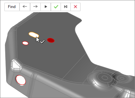
Select the Hole icon.

By default, all of the holes in the model are selected and highlighted red. The total number of holes found is displayed above the Defeature tool group.
- Fill holes.
- Fill all selected holes by clicking
 on the guide bar.
 - Fill individual holes by left-clicking on a selected hole.
 and
and  . To fill a hole, select it and left-click. The view
automatically zooms to the next hole.
. To fill a hole, select it and left-click. The view
automatically zooms to the next hole.Fill Cutout
Use the Fill Cutout tool to find and fill cutouts in the model.
-
On the Feasibility tab, click the Defeature icon.
-
Select the Cutout icon.

-
Left-click to select the start and end points of the cutout.
Identified cutouts are selected and highlighted red.
-
Fill cutouts.
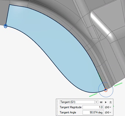
- Enter a Tangent Magnitude in the microdialog to adjust the magnitude of the blend curve at the selected point.
- Enter a Tangent Angle in the microdialog to adjust the angle of the blend curve at the selected point.
- To fill the selected cutouts, on the guide bar, click .
- Fill individual cutouts by left-clicking on a selected cutout.
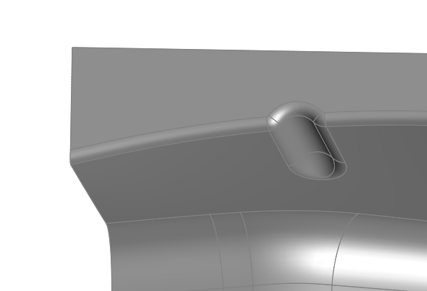
Fillet
Use the Fillet tool to remove filleted edges on the selected part.
-
On the Feasibility tab, click the Defeature icon.
-
Select the Fillet icon.

-
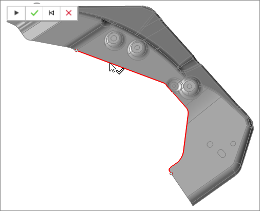
Click Find in the guide bar, which allows Inspire Form
to find and highlight edge fillets on the part in red. Use the arrows to
navigate between fillets. Press the reset button
 to
clear your selections and begin again.
to
clear your selections and begin again.
-
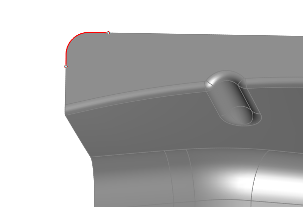
Click the Delete Fillet button in the guide bar to
remove the selected filleted edges. You can also manually select the fillets
you'd like to delete by clicking on them individually, and then selecting
Delete Fillet.
- Right-click and mouse through the check mark to exit, or double-right-click.
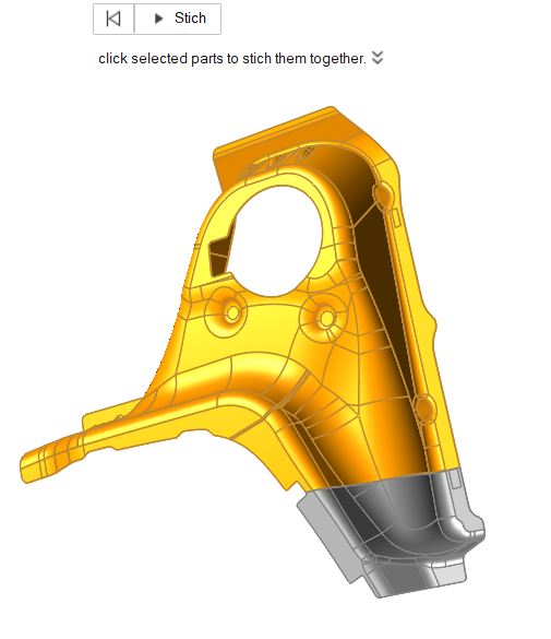
Stitch
Use the Stitch tool to combine multiples surfaces or parts.
-
On the Feasibility tab, click the Defeature icon.
-
Select the Stitch icon.

-
Left-click to select the surfaces of the part that you want to fill and combine
into a single surface. Empty, non-integrated, surfaces/patches on the part will
appear in gray.
-
Click all of the gaps and then press
 in the microdialog.
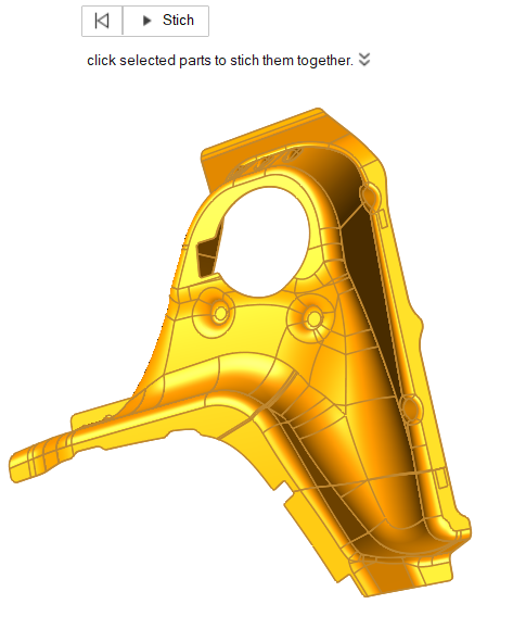
- Repeat Steps 3 and 4 until all of the gaps are filled and the part is stitched together into a whole, complete surface.
- Right-click and mouse through the check mark to exit, or double-right-click.
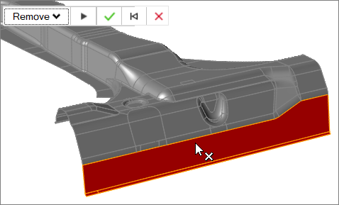
Remove Surfaces
Use the Remove tool to remove surfaces from a part.
-
On the Feasibility tab, click the Defeature icon.
-
Select the Remove icon.

-
Left-click to select surfaces.
Surfaces are automatically detected and highlighted based on your cursor position.
Selected surfaces are highlighted red. The total number of selected surfaces is displayed above the Defeature tool group.
-
Remove surfaces.
- Select to Remove or Partition surfaces in the guide bar.
- Left-click a surface you would like to remove or partition.
-
Click
 on the guide bar to remove or partition all
selected surfaces.
on the guide bar to remove or partition all
selected surfaces.
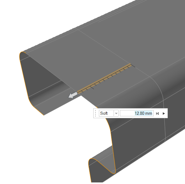
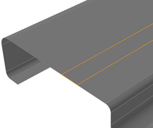
Extend
Use the Extend tool to extend a surface.
-
On the Feasibility tab, click the Defeature icon.
-
Select the Extend icon.

-
Left-click to select edges.
Edges are automatically detected and highlighted based on your cursor position.
Selected edges are highlighted red.
- Select Linear or Soft.
-
Enter a distance to extend, or drag the edge to extend the surface.
-
Click Apply
 .
.
Unflange
Use the Unflange tool to open a flange to a reference surface or to open a bend.
-
On the Feasibility tab, click the Defeature icon.
-
Select the Unflange icon.

-
On the guidebar, select Unflange to open flanges or
Unbend to open bends.
Note: When using Unbend, you can click the K Factor Option
 and enter a K factor value to
calculate the bend allowance when unfolding bends. The range is 0 to 0.5,
and the default is 0.5.
and enter a K factor value to
calculate the bend allowance when unfolding bends. The range is 0 to 0.5,
and the default is 0.5.
Open a Flange
-
Left-click to select flanges, then left-click again to confirm selection.
Flange surfaces are automatically detected and highlighted based on your cursor position.
Selected flange surfaces are highlighted red.
Press Ctrl and left-click to deselect a flange surface.
-
Select Reference on guidebar then select reference
surfaces to unflange on.
Selected reference surfaces are highlighted red.
Press Ctrl and left-click to deselect a reference surface.
- Click Apply to open flanges.
Open a Bend
-
Left-click to select bends to open.
Surfaces are automatically detected and highlighted based on your cursor position.
Selected bent surfaces are highlighted red.
Press Ctrl and left-click to deselect a bent surface.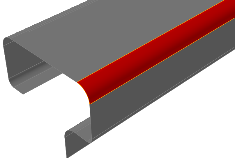
-
Left-click to open bends, or click Apply.
Keyboard Shortcuts & Mouse Controls
| To | Do this |
|---|---|
| Select feature | Click |
| Deselect feature | Ctrl+click |
| Exit tool | Right-click and mouse through the check mark to exit, or double-right-click. |