DC winding
Terminology and definitions
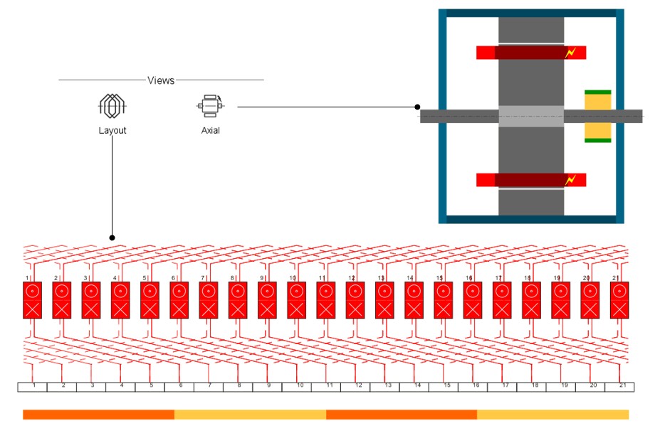
Concept
A DC winding is formed by as many individual coils as the number of slots of the machine. All these coils are identical except for an angular shift. Since the coils have an input slot and an output one, a slot will always have two coils wound inside it.
A key characteristic of a DC winding is that, unlike the 3-phase one, a coil is characterized (other than by its input and output slots) by the two commutator segments connected to it (one for the input side and a second for the output side). These commutator segments will connect the coil to the brushes and, therefore, to the DC source feeding the machine.
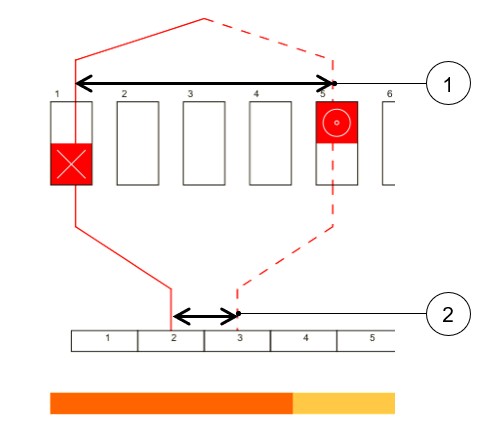
- The throw – The coil pitch number of slot pitch between coil input and coil output.
- The commutator pitch: the number of commutator segments between the segment connected to the coil input and the segment connected to the coil output.
 |
|
|---|---|
| 1 | Throw |
| 2 | Commutator pitch |
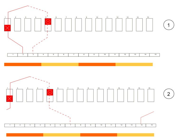
These two parameters are not chosen randomly but to optimize the electromotive force. Two main types of winding exist: wave winding and lap winding.
- Lap winding: The ends of one coil are connected to consecutive commutation segments (i.e., the commutator pitch absolute value is equal to 1 for simplex winding)
- Wave winding: The ends of one coil are connected to commutator segments separated by an angular distance as close as two pole pitch as possible (for simplex winding)
For both winding types, the throw is usually as close as possible to a pole pitch.
- The plex defines the number of commutator segments in contact with the same brush at a given time. It has a great influence on the number of parallel paths and, therefore, on the machine’s back EMF and the maximum current.
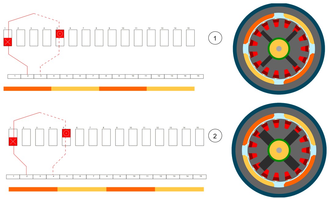
- The coil connection can be progressive or regressive: In a progressive connection the commutator segments are connected following the same direction as the winding (i.e., commutator pitch is positive) while in a regressive connection the commutator segments are connected following the opposite direction as the winding (i.e., commutator pitch is negative).
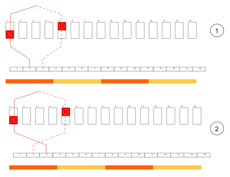
Winding type
 |
|
|---|---|
| 1 | Lap winding example |
| 2 | Wave winding example |
Plex
 |
|
|---|---|
| 1 | Simplex winding |
| 2 | Duplex winding |
Coil connection
 |
|
|---|---|
| 1 | Progressive winding |
| 2 | Regressive winding |
Winding Architecture – Outputs
Introduction
Output is quite like 3-phase winding, but some specific parameters arise when dealing with DC machine winding. For the sake of completeness, the parameters are listed in the tables below.
Characterization - Winding
| Label | Tooltip, note, formula |
|---|---|
| No. poles | Number of rotor pole pairs =p. 2p = number of poles. |
| No. slots | Number of stator slots |
| No. Layers | Number of layers – For a DC winding it is always equal to 2 |
| Winding type | The winding type: Lap or wave |
| Plex | The plex (simplex, duplex or triplex) |
| Coil connection | Connection type: Progressive or regressive Progressive connection: Commutator segments are connected following the same direction as winding (i.e., commutator pitch is positive). Regressive connection: Commutator segments are connected following the opposite direction as winding (i.e., commutator pitch is negative). |
| Commutator pitch | Number of commutator segments between the segment connected to the coil input and the segment connected to the coil output. |
| No. parallel paths | Number of parallel paths. For a wave winding it is equal to twice the plex. For a lap winding it is equal to number of poles * plex |
| Coil layout | Coil layout inside the slot – Full, Superimposed or Adjacent. |
| Throw (coil pitch) | Number of slot pitch between coil input and coil output. |
Characterization - Coil
| Label | Tooltip, note, formula |
|---|---|
| No. turns per coil | Number of turns per coil. |
| No. turns in series | Number of turns in series N_turns=N_coils/(2×P_paths ) Where Ncoils is the total number of coils and Ppaths the number of parallel paths |
| No. conductors | Total number of conductors N_coils=2×N_slots×Turns Where Ncoils is the total number of coils and Nslots is the number of slots and Turns is the number of turns per coil. |
Lengths
| Label | Tooltip, note, formula |
|---|---|
| Total conductor length | Total conductor length. |
| Mean turn length | Mean turn length. |
| Coil connection length | Additional length corresponding to the connections between coils and commutator segments. |
| Axial overall length | Axial overall length. Length between the two extremities of the winding i.e. between connection side and opposite connection side. |
Areas in slot
| Label | Tooltip, note, formula |
|---|---|
| Conductive area | Conductive area inside one slot. A_CondSlot=A_Cond×Turns Where Turns is the number of turns per coil. |
| Conductor conductive area | A_Cond=N_wires×A_wire This area allows to compute the current density. |
| Wire conductive area | Wire area (without insulation) = A_wire |
| Slot area | Slot area = A_slot |
| Insulation area | Insulation area inside one slot =A_InsulSlot One considers the slots of the machine where the number of coils is maximum. |
| Free area | A_Free= A_slot- A_CondSlot- A_InsulSlot |
Fill factors
| Label | Tooltip, note, formula |
|---|---|
| Gross fill factor | Gross fill factor. Occupancy rate of the slot (conductive area only). (Conductor conductive area)/(Slot area)×100 |
| Net fill factor | Net fill factor. Occupancy rate of the slot (conductive area + insulation area). (Conductor conductive area+insulation area)/(Slot area)×100 |
Resistances
| Label | Tooltip, note, formula |
|---|---|
| Single coil resistance | Single coil resistance |
| Parallel path resistance | Resistance of one of the parallel paths |
| Total resistance | Total resistance of the machine at its terminals |
| Winding straight part resistance |
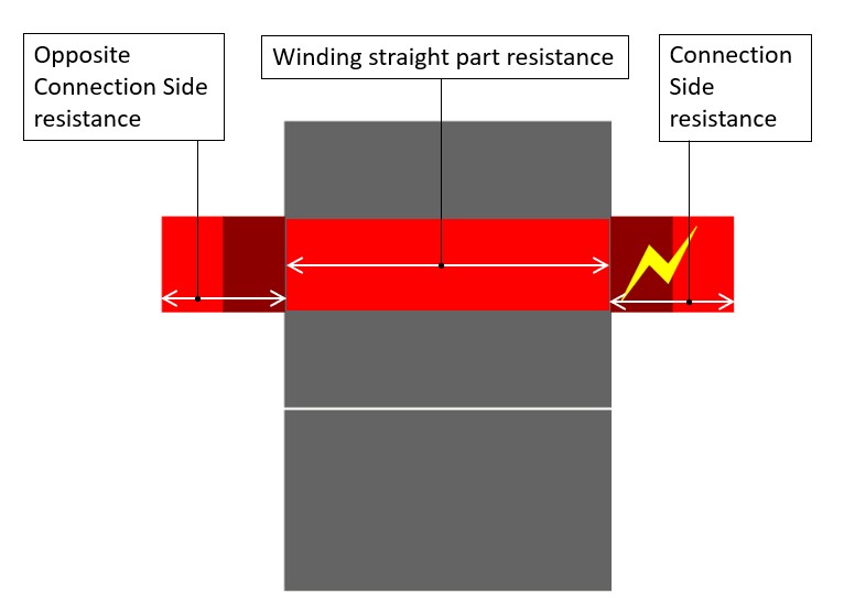 |
| End-winding resistance | |
| Connection side end-winding resistance | |
| Opposite connection side end-winding resistance |
Inductances
| Label | Tooltip, note, formula |
|---|---|
| End winding | Total end winding inductance (including the two sides of the machine). |
| C.S. end winding | Connection side end winding inductance. |
| O.C.S. end winding | Opposite connection side end winding inductance. |
Masses and costs
| Label | Tooltip, note, formula |
|---|---|
| Total | Total winding mass. |
| Electric conductor | Conductive part mass. |
| Total insulation | Total winding insulation mass (wire + conductor + coil insulation + liner + phase separator). |
| Wire insulation | Wire insulation. |
| Conductor insulation | Conductor insulation. |
| Coil insulation | Coil insulation. |
| Liner insulation | Liner insulation. |
| Phase separator insulation | Phase separator insulation. |
| Impregnation insulation | Impregnation insulation |
| Wedge insulation | Wedge insulation, only when the slot topology contains a wedge |
Visualization of the winding architecture