Classical & hairpin
Introduction
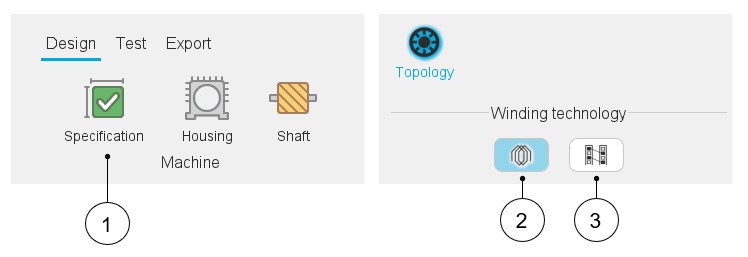
In Motor Factory, when the classical winding type or the hairpin winding type can be considered, this choice must be done in the Design area, in the environment “Specification”.
 |
|
|---|---|
| 1 | In Motor Factory – Design environment – Select the specification – Section “Topology” |
| 2 | Classical winding technology |
| 3 | Hairpin winding technology. Note: Hairpin
winding technology is available only for the 3-Phase inner rotor
machine. |
3-Phase and polyphase windings
The polyphase nature of the winding is not an option available in the machine specification. To design a polyphase machine, the user must select the appropriate machine type.
Structural data - Validity domain
The number of slots can be chosen over the range [3, 2400].
The number of poles can be chosen over the range [2, 400].
The number of phases can be chosen over the range [3,15]. Only odd values are considered.
- Range for number of slots [3, 90]
- Range for number of poles [2, 80]
- Range for number of phases [3,15]
Working beyond these bounds is possible, but accuracy of the results is the responsibility of the user.
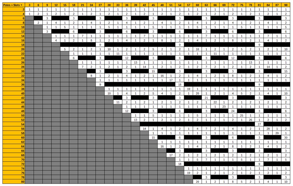
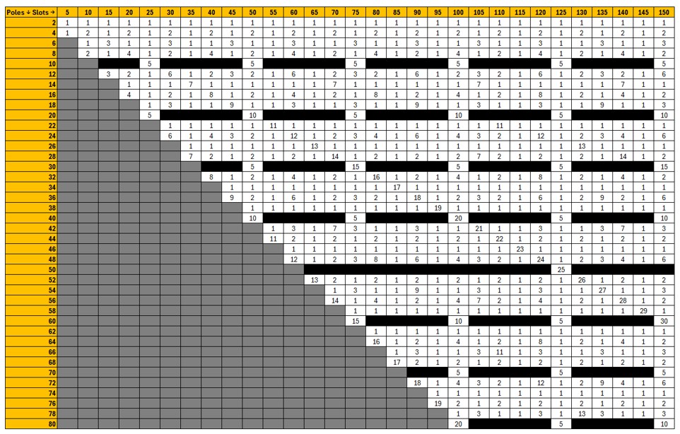
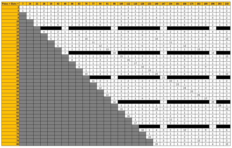
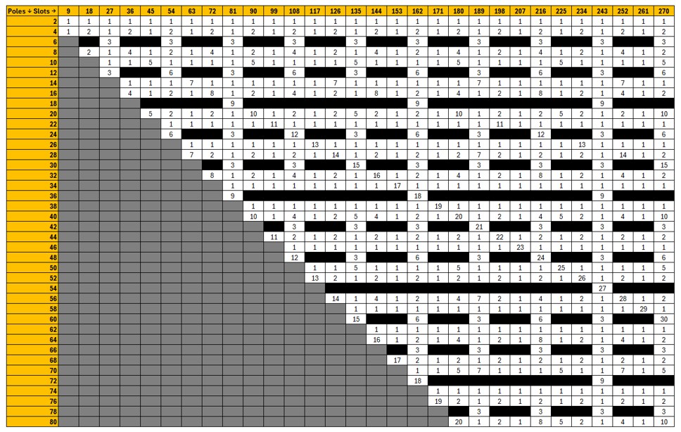
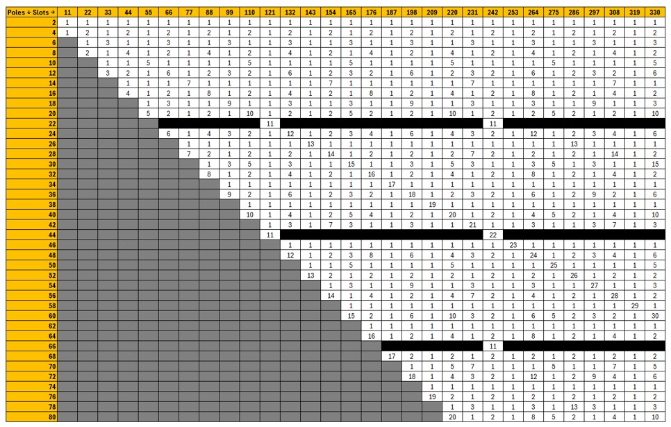
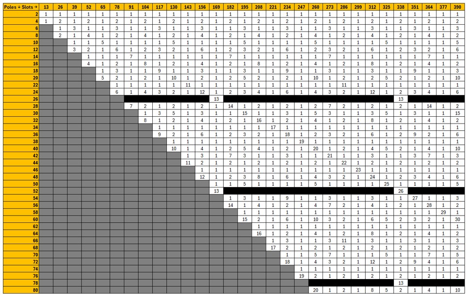
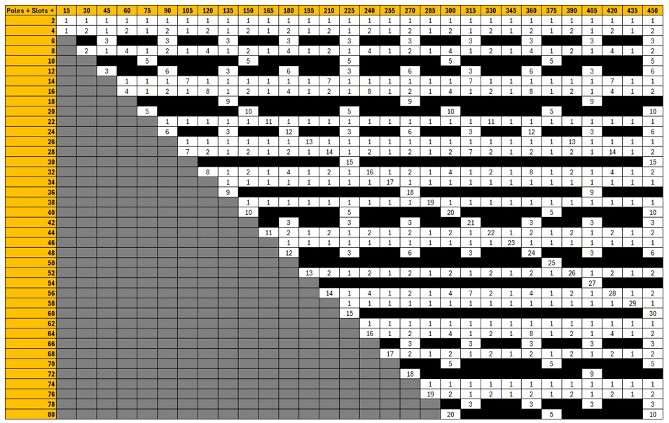
Three tables representing a selection of combinations of number of poles and number of slots for the most typical number of phases (three, five and seven) are presented below.
- For three-phase machines, the grey cells correspond to combinations with
a number of slots per pole per phase strictly lower than 0.25. These
cases are not allowed by our process.
Note: if the hairpin winding type is selected, only configurations with an integer number of slots per pole and per phase are allowed.
- The black cells correspond to forbidden combinations from a technological point of view.
- The numbers indicated in the other cells correspond to reduction coefficients to the resulting model in Altair Flux. For example, “1” means that the whole geometry is represented. “2” means that only half of the machine is represented, and “n” means that the 1/nth of the geometry is represented in the Flux® environment. That means it gives a general idea of the size of the model in Altair Flux software. Higher value gives the reduction coefficient and faster computation for a given motor.
Terminology – Illustration
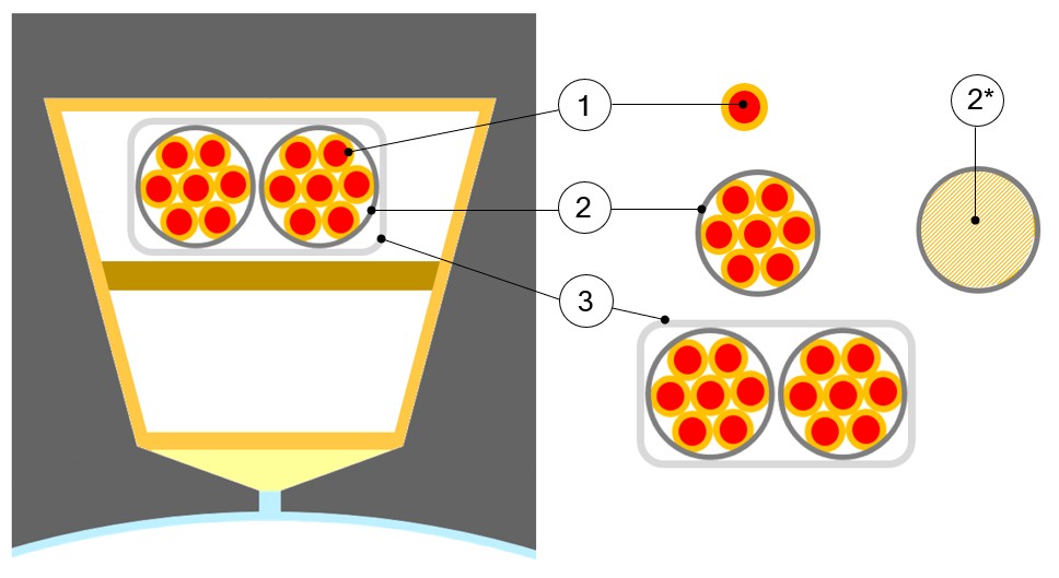
Slot composition - Terminology
 |
|
|---|---|
| 1 | Wire (also called strand) |
| 2 | Conductor, that also corresponds to a turn section (one conductor
= one turn). A conductor is composed of one or several wires in parallel (wires in hand). |
| 2* | The hatched area corresponds to the conductor’s useful area. Area that includes: the wires + insulation + free space. This is not the conductive area. |
| 3 | Coil, which is an assembly of several conductors (i.e. several turns per coil). |
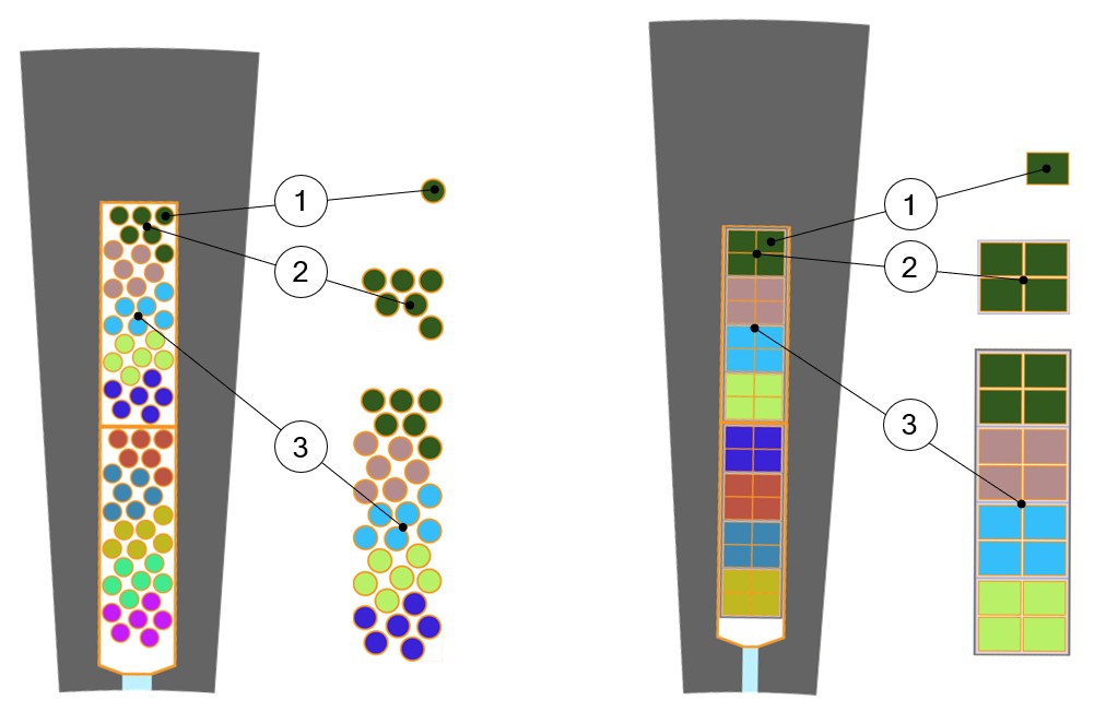
Slot composition
 |
|
|---|---|
| 1 | Wire (also called strand) |
| 2 | Conductor (also called bundle). That also corresponds to a turn
section (one conductor = one turn). A conductor is composed of one or several wires in parallel (wires in hand). |
| 3 | Coil, which is an assembly of several conductors (i.e. several turns per coil). |
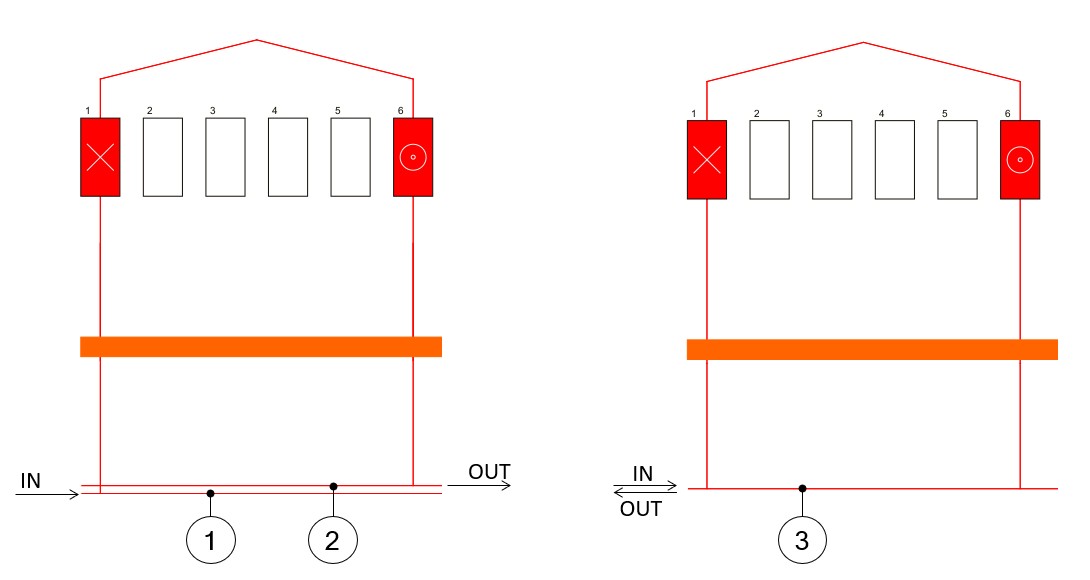
Layout of the winding – Connections
The lines that collect incoming and outgoing connections are merged into a single line. This has been done to make polyphase winding diagrams easier to read. The picture below illustrates the principle of representation.
 |
|
|---|---|
| 1 - 2 | The two-line connection, which represents the incoming and outgoing connections. |
| 3 | In the winding layout, only one line corresponds to both IN and OUT connections. |
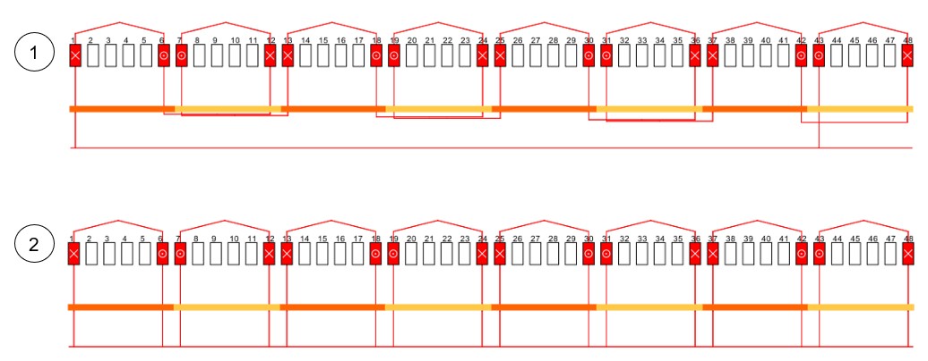
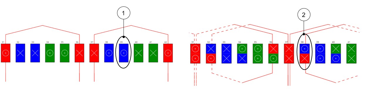
Parallel paths
Depending on the number of phases, poles and slots, parallel circuits can be realized in the winding scheme.
 |
|
|---|---|
| 1 | Example where the number of parallel paths is equal to 1. |
| 2 | Example where the number of parallel paths is equal to 8. |
Number of layers
 |
|
|---|---|
| 1 | Example, where the number of layers is equal to 1. |
| 2 | Example, where the number of layers is equal to 2. |
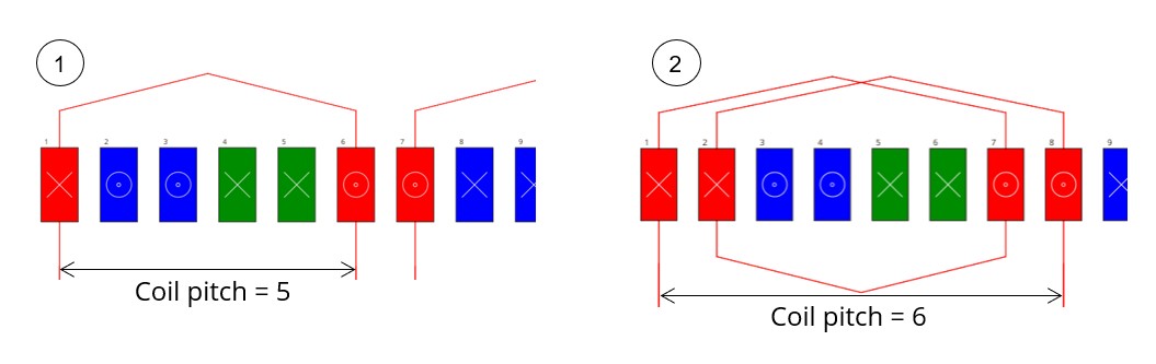
Coil pitch
The coil pitch corresponds to the number of teeth between the notch where the coil conductor enters and the notch or coil conductor exits. Here is an Illustration of the coil pitch.
 |
|
|---|---|
| 1 | Example, where the coil pitch is equal to 5 - from slot 1 to slot 6 (6-1 = 5). |
| 2 | Example, where the coil pitch is equal to 6 - from slot 1 to slot 7 (7-1 = 6). |
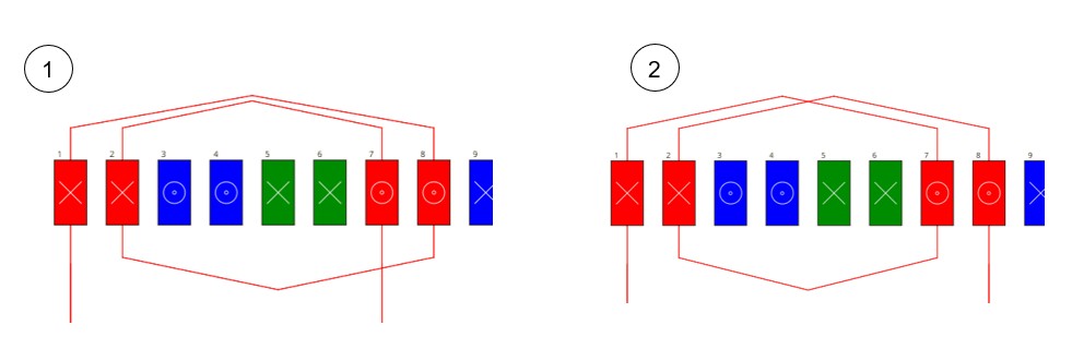
Winding type
 |
|
|---|---|
| 1 | Example for the Concentric winding type. |
| 2 | Example for the Lap winding type. |
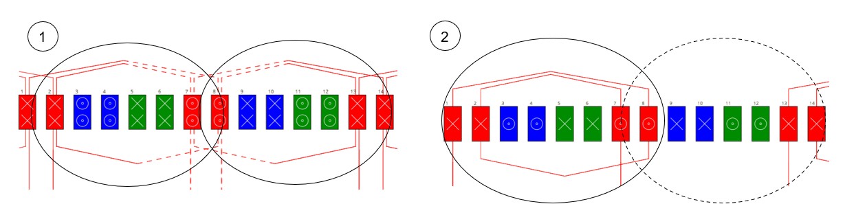
Pole distribution
Generally, each pole corresponds to a group of winding coils. However, when a phase has only one group of coils per pair of poles instead of two, the winding is called a consequent pole winding. These two configurations are illustrated below.
 |
|
|---|---|
| 1 | Example for the Per pole winding type. |
| 2 | Example for the Consequent winding type. |
Coil layout in slot
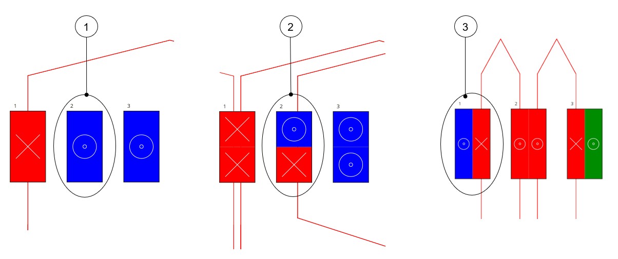
There are three possible coil layouts in slot: Full, superimposed or adjacent. These three configurations are illustrated below.
 |
|
|---|---|
| 1 | Example where the coil layout is Full. |
| 2 | Example where the coil layout is Superimposed. |
| 3 | Example where the coil layout is Adjacent. |
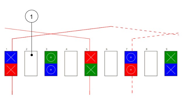
Winding customization
 |
|
|---|---|
| 1 | The result is that there are slots without coils. The
relevance of the winding architecture depends on the user. A
quality criterion allows verifying this relevance. Note: Example with 8 poles, 48 slots, coil
pitch =10 |
Winding outputs
Winding - Characteristics
Winding factors (Fundamental)
For the hairpin winding technology, for unbalanced hairpin configurations, as these results are not relevant, they are not computed and “-“ is displayed instead.
Unbalanced hairpin configurations are characterized by at least one parallel path that is different in terms of voltage and impedance from the other parallel paths.
Coil
- Case of classical winding technology
Figure 10. Case of classical winding technology 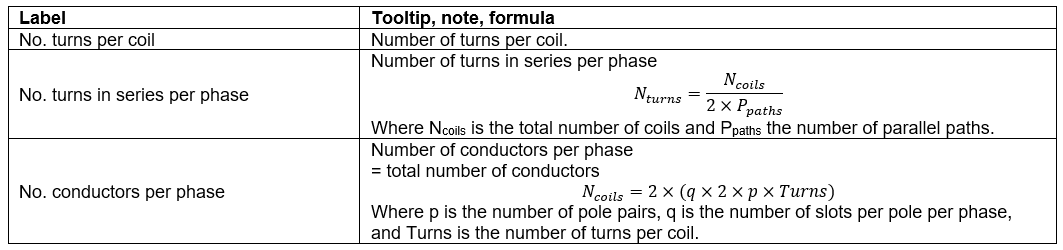
- Case of hairpin winding technology
Figure 11. Case of hairpin winding technology 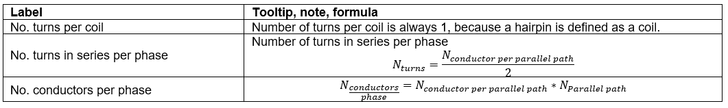
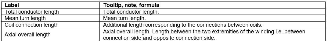
Lengths
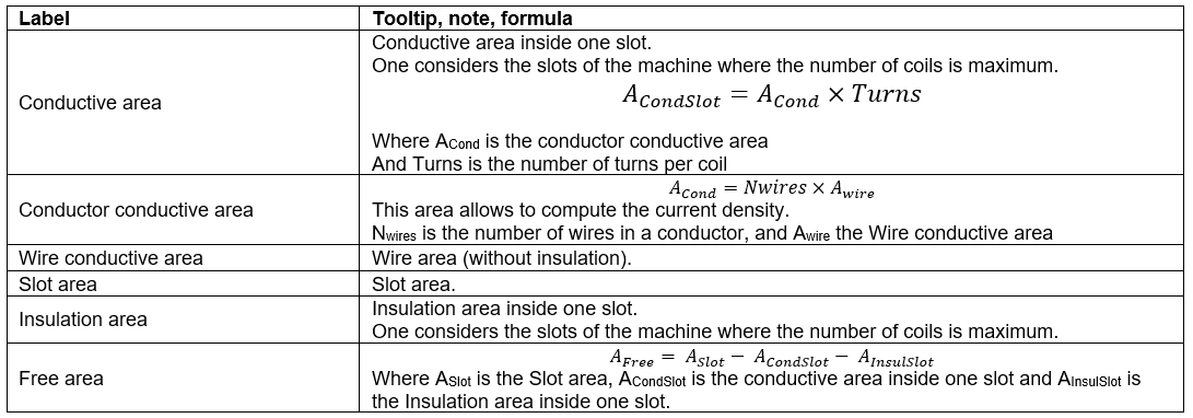
Areas in slot
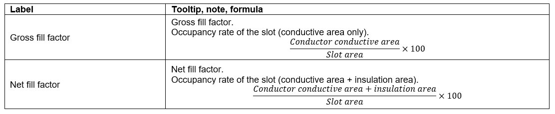
Fill factors
Resistances
- Case of classical winding technology
Table 12. Resistances Label Tooltip, note, formula Phase resistance Phase resistance Line-Line resistance Line-Line resistance Winding straight part resistance 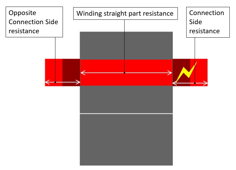
Connection side end-winding resistance Opposite connection side end-winding resistance Note: The reference temperature is a user input parameter defined in the winding – X-Factor tab.Note: The connection side end-winding resistance considers the additional length corresponding to the connection between coils. - Case of the hairpin winding technology
Table 13. Resistances Label Tooltip, note, formula Phase resistance Phase resistance Line-Line resistance Line-Line resistance Parallel path number Number of parallel paths Parallel path resistance Value of parallel path resistance Winding straight part resistance
End-winding resistance Connection side end-winding resistance Opposite connection side end-winding resistance Note: The reference temperature is a user input parameter defined in the winding – X-Factor tab.Note: The connection side end-winding resistance considers the additional length corresponding to the connections between coils.Note: For each parallel path, the resistances are computed and displayed for the winding straight part and the end-winding part (at the connection side and at the opposite connection side).
Inductances
- Case of classical winding technology
Table 14. Label Tooltip, note, formula End winding Total end winding inductance (including the two sides of the machine). C.S. end winding Connection side end winding inductance. O.C.S. end winding Opposite connection side end winding inductance. - Case of the hairpin winding technology
Table 15. Label Tooltip, note, formula Phase Phase inductance Parallel path number Number of parallel paths End winding Total end winding inductance (including the two sides of the machine). C.S. end winding Connection side end winding inductance. O.C.S. end winding Opposite connection side end winding inductance. Note: For each parallel path, the end winding inductances are computed and displayed for the Connection Side and for the Opposite Connection Side.
Masses and costs
| Label | Tooltip, note, formula |
|---|---|
| Total | Total winding mass. |
| Electric conductor | Conductive part mass. |
| Total insulation | Total winding insulation mass (wire + conductor + coil insulation + liner + phase separator). |
| Wire insulation | Wire insulation. |
| Conductor insulation | Conductor insulation. |
| Coil insulation | Coil insulation. |
| Liner insulation | Liner insulation. |
| Phase separator insulation | Phase separator insulation. |
| Impregnation insulation | Impregnation insulation |
| C.S. potting | Connection Side potting |
| O.C.S. potting | Opposite Connection Side potting |
| Wedge insulation | Wedge insulation, only when the slot topology contains a wedge |
Visualization of the winding architecture
- Case of classical winding technology
Figure 15. Visualization of the winding architecture 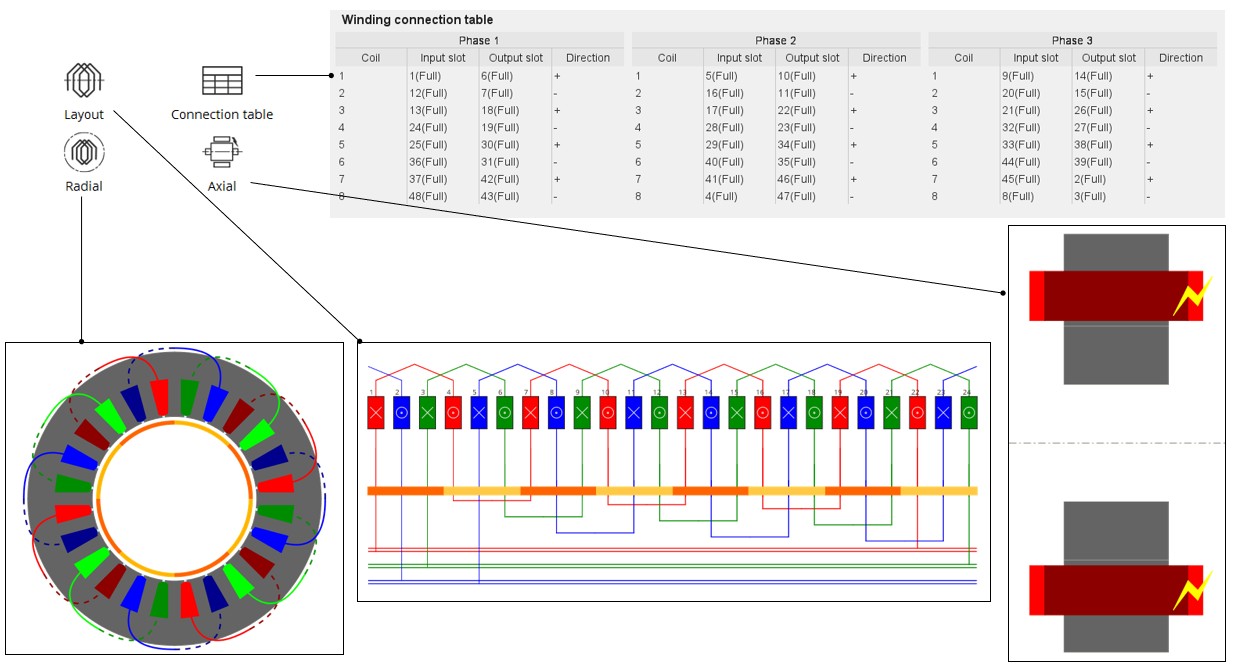
- Case of the hairpin winding technology
Figure 16. Visualization of the winding architecture 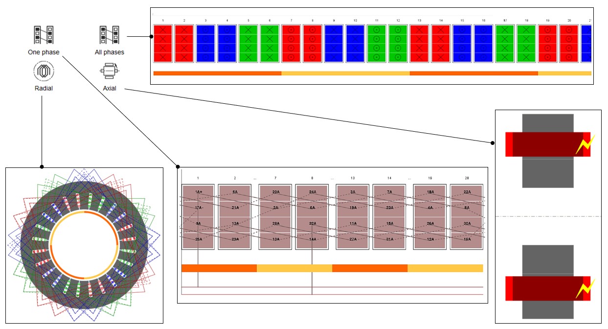
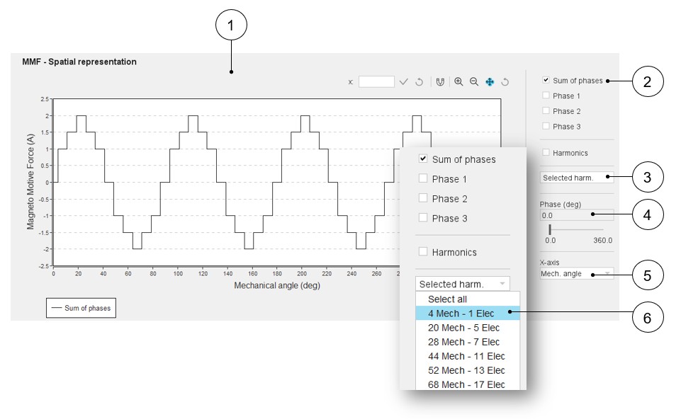
Magneto-Motive Force analysis
 |
|
|---|---|
| 1 | Select the spatial representation of the Magneto-Motive Force (M.M.F.) |
| 2 | Check the curves to display. Sum of phases M.M.F or M.M.F.
provided by each phase. Note: Superimposition
of harmonics is possible only if one or several harmonics have
been selected. See explanation below. |
| 3 | Visualize the harmonic list of the M.M.F. |
| 4 | Select the phase and make the M.M.F. signal slide. That shows the direction of rotation of the M.M.F... This illustrates the relevance of the phase sequence (user input). |
| 5 | Mechanical angle or slot number can be chosen for the X-axis. |
| 6 | Select one or several harmonics to superimpose with the original M.M.F. signal. |
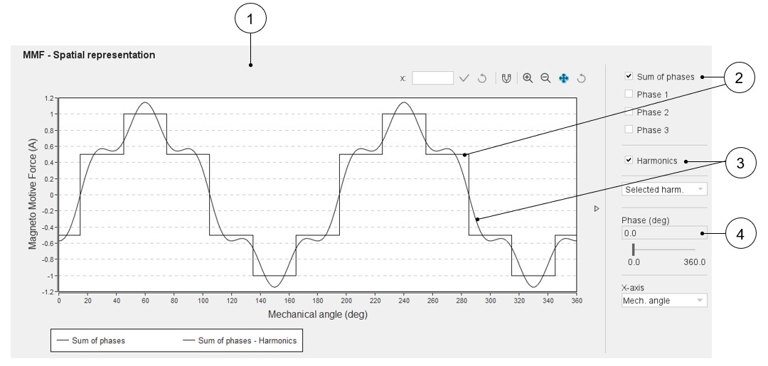 |
|
|---|---|
| 1 | Select the spatial representation of the Magneto-Motive Force (M.M.F.). |
| 2 | Check the curves to display. Sum of phases, for example. |
| 3 | Check Harmonics. The harmonics previously selected in the M.M.F. harmonic table are superimposed with the original M.M.F. signal. |
| 4 | The selected phase is equal to 0. |
Quality criteria
- Winding factor
Table 19. Winding factors 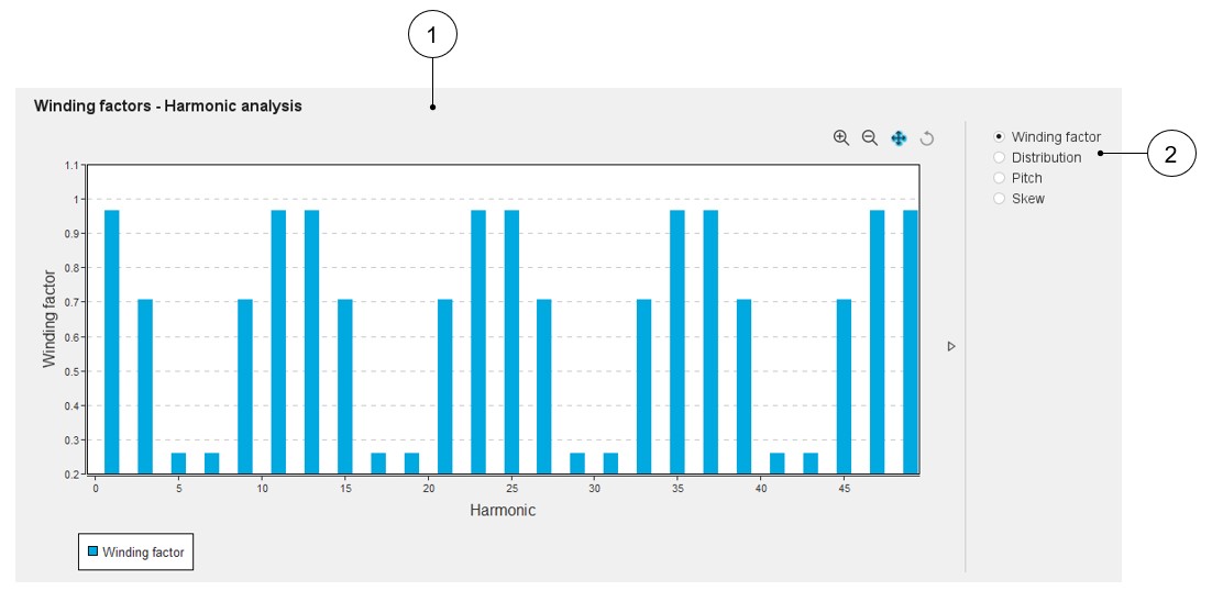
1 Select the winding factor bar-graph. 2 Checking the different winding factors allows visualizing the corresponding bar graph. Note: Skew factor is computed when the skewing of the stator slots is considered. Without slot skewing, this factor is always equal to 1.Note:For unbalanced hairpin configurations, as the results are not relevant, therefore, they are not computed and displayed.
The unbalanced hairpin configurations are characterized by at least one parallel path that is different in terms of voltage and impedance from the other parallel paths.
- Slot star
- Case of classical winding technology
Table 20. Star slot. Example for 5-Phase machine 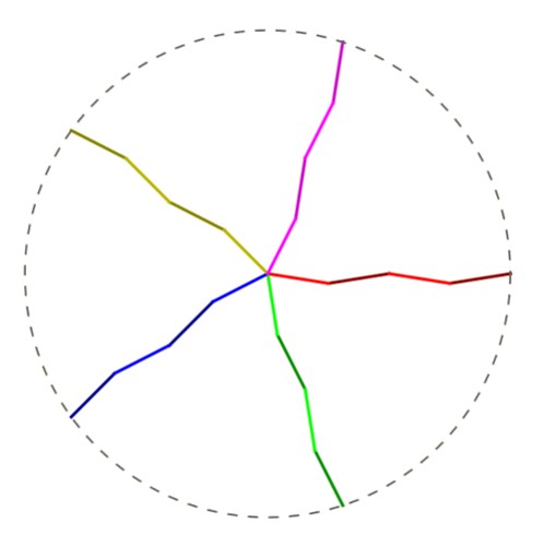
1 The Slot star represents the total vector summation of voltages at the ends of each coil. - Case of the hairpin winding technology
Table 21. Slot star - Strong or weak balance case example 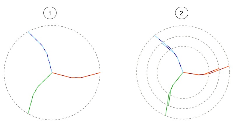
Slot star - Strong or weak balance case example Slot star - Unbalanced case example Note: Balance analysis classification:When the hairpin configuration is balanced (strong and weak balance), all the slot stars are superimposed (to differentiate strong and weak balance cases referred to in the table Parallel paths).
When the hairpin configuration is unbalanced, there are as many different slot stars (circles) as there are different unbalanced parallel paths.
Note: Definition of Strong and weak balance are done below.
- Case of classical winding technology
- Current balance of parallel paths
Only applicable for hairpin winding technology
For each slot per pole and per phase of each parallel path, the number of conductors in each conductor layer is computed and displayed in a table.
The three kinds of possible configurations in terms of electrical current in parallel paths are illustrated below: Strong balance, weak balance and unbalance.
Figure 17. Current balance of parallel paths – Strong balance case example 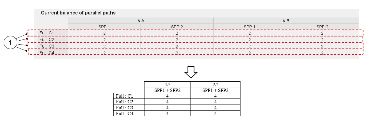
Figure 18. Current balance of parallel paths – Weak balance case example 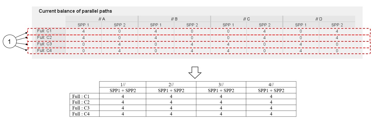
Table 22. Current balance of parallel paths – Unbalance case example 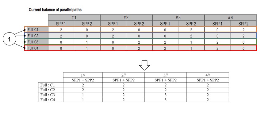
1 Layer of conductors 2 Balance analysis classification: Balance analysis classification:- When the same number of conductors are displayed in all the cells, a “strong balance hairpin configuration” is obtained. This is the best winding design configuration.
- If for each parallel path and all layers of conductors the sums of conductors are the same, a “weak balance hairpin configuration” is probably obtained (to be confirmed with the slot star if all the circles are well superimposed).
If for each parallel path and all layers of conductors the sums of conductors are different, an “unbalance hairpin configuration” is obtained.
- Voltage drop
Table 23. Conductor voltage drop 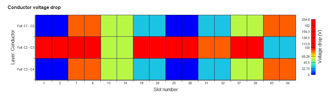
1 Inside each slot, the voltage drops between the superimposed conductors for calculating the maximum Line-Line voltage value and the voltage drop limit set by the user (X-factor: model evaluation table). This allows the user to quickly visualize where the hot points are from an electrical potential difference point of view.