Since version 2026, Flux 3D and Flux PEEC are no longer available.
Please use SimLab to create a new 3D project or to import an existing Flux 3D project.
Please use SimLab to create a new PEEC project (not possible to import an existing Flux PEEC project).
/!\ Documentation updates are in progress – some mentions of 3D may still appear.
Explanation of results: computation of flux carried out by Flux
Reminder: link FE/circuit
Here is a reminder about the link between the finite elements domain and the electrical circuit:
| CIRCUIT | FINITE ELEMENTS |
|---|---|
| In an electrical circuit, there are: | In the finite element domain,there are: |
| Component of coil conductor type |
Region of coil conductor type or No meshed coil (only in 3D) |
| Component of solid conductor type | Region of solid conductor type |
Availabilities of flux computation
The table below allows to accurate the availabilities of flux computation in function of the dimension and the method.
| 2D plane | 2D axi | 3D | ||
|---|---|---|---|---|
| Circuit | Computation on a component of coil conductor type | |||
| Computation on a component of solid conductor type | ||||
| Finite Elements | Computation on region |
|
|
|
Computation on a region
The used formula in the Flux software for the computation of flux on a region is:
Flux : ![]()
with ![]()
J : current density
i : current in one turn
φ : flux across one turn
A : potential vector
S : region area
V : region volume
n : number of turns
Computation on a coil conductor in 2D
The computation flux on a coil conductor in 2D is equivalent to the formula of the computation on a region, detailed on the previously block.
The formula is applied on all regions which the coil conductor is assigned.
Computation on a coil conductor in 3D
The following computation is only applicable for the computation of the flux on a coil conductor in 3D.
The coil conductor can be used to model a coil of type « imposed current » or « coupled circuit »:
- by a region of coil conductor type
- by a no meshed coil
The flux Φk in a coil k is expressed by the derivative of the magnetic co-energy Wm' with respect to the current Ik in this coil:
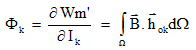
hok : is the field created by the coil k in the vacuum when the carrying current is 1A
![]() : is the study
domain
: is the study
domain
The command is applied for an electric component of Coil conductor type) and not directly for a coil because several coils can be regrouped by means of a component (typically in the cases of symmetry and/or periodicity).
The computed flux is a total flux “embraced” by an assembly of turns, for all the coils “belonging” to the electrical component. The number of turns is the total number of turns, i.e. the sum of the number of turns of each coil.
3D specificity for no-mesh coil: The accuracy of the results depends on the mesh, and in particular on the mesh around the coils. For a better precision of the magnetic flux computation, it can be useful to geometrically describe the coils and to mesh it. The precision is increased when second-order elements are used
Inductance: self/mutual
For a linear model, after to compute the flux the user can deduce the equivalent inductance.
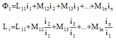
If several coils are current supplied at the same time, the computed inductance is a global inductance L which includes the self inductance of the chosen coil L11 and the mutual inductances due to the other supplied coils M12, M13…
To compute the self inductance of a coil, the current in the other coils must be zero. In these conditions, this value can also be obtained by calculating the global energy W of the system:
![]()
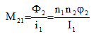
The flux flowing through the non-supplied coils (I2 = 0, I3 = 0, ...) allows you to deduce their mutual inductance with the supplied coil:
The computation of the matrix of inductances of a device requires a solution for each supplied coil.
Inductance 2D modelisation rules
The modeling of a coil is different in function of the used case. The deduction of the coil inductance can be different.
The table below shows the necessary information about the computation of the coil inductance according to the used modeling:
| Deduction of an inductance | Complements | ||
|---|---|---|---|
| 2D plane | without symmetries / periodicities |
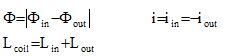
If the in and out regions of a coil are described, the inductance of this coil is equal to the sum of the inductances computed for the in and out regions:
|
The in and out regions of each coil must be current supplied simultaneously so that the device studied is in equilibrium (integral of the sources equal to zero) |
| with symmetries / periodicities |
If only the out region is described due to symmetries or periodicities, the inductance of this coil is equal to twice the inductance computed for the out region
|
In the plane and without infinite box, if only the out part of the coil has been described due to symmetry, the in part must imperatively be simulated by the boundary conditions. If this condition is not applied the values of inductance obtained may be incorrect | |
| 2D axi |
The inductance computed for a region is the inductance of the corresponding coil:
|
Only one region is necessary to describe a coil, so only one current supplied. The device is automatically in equilibrium. | |
Flux and symmetries/ periodicities
If the modeled device has symmetries and/or periodicities:
- For a computation on a component, Flux takes into account the “original” coils and their “copies” by symmetry and/or periodicity.
In this case Flux evaluates:
- a specific coefficient that takes into account the number and the type of symmetries and/or periodicities
- the Conductors in series or in parallel command that takes into account the association type of coils (all in series, all in parallel)
- For a computation on a region, flux only takes into account the represented part without take into account symmetry and/or periodicity. In this case, the user must apply the coefficient with the obtained result.