Since version 2026, Flux 3D and Flux PEEC are no longer available.
Please use SimLab to create a new 3D project or to import an existing Flux 3D project.
Please use SimLab to create a new PEEC project (not possible to import an existing Flux PEEC project).
/!\ Documentation updates are in progress – some mentions of 3D may still appear.
3D Example: Rear view motor analysis (Technical paper)
Foreword
This paragraph is a summary of cases studied in the technical document: " Rear-view mirror motor analysis ".
The files relating to the studied cases are accessible via the supervisor.
Study carried out
The study proposed in the technical paper "Rear-view mirror motor analysis" is the study of a DC motor used to align the rear-view mirror of a car.
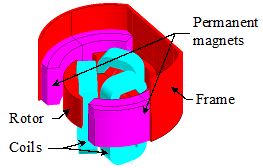
Studied device
- a fixed part composed of a frame and two permanent magnets
- a movable part composed of a three-pole rotor with triangle-connected coils
Operating principle
The operation of a simple DC electric motor is explained below:
- When the coil is powered, a magnetic field is generated around the armature. The left side of the armature is pushed away from the left magnet and drawn toward the right, causing rotation.
- The armature continues to rotate.
- When the armature becomes horizontally aligned, the commutator reverses the direction of current through the coil, reversing the magnetic field. The process then repeats.
Studied cases
Five cases are carried out:
- case 1 and 2: studies using a multi-static kinematic model
- case 3: a transient study using an imposed speed kinematic model
- case 4: a transient study using a coupled load kinematic model
- case 5: a parametric study to compute the end winding inductance
Case 1
The first case is a study using a multi-static kinematic model (Magneto Static application).
In this study rotor takes different static positions; the material used for the frame and the rotor is stainless steel with constant relative permeability (linear B(H) characteristic).
We are interested in the computation of the cogging torque due to the magnetic field produced by permanent magnets at various rotor angular positions.
Case 2
The second case is a study using a multi-static kinematic model (Magneto Static application).
In this study rotor takes different static positions; the material used for the frame and the rotor is stainless steel with nonlinear B(H) characteristic.
We are interested in the computation of the cogging torque due to the magnetic field produced by permanent magnets at various rotor angular positions.
Case 3
The third case is a study using an imposed speed kinematic model (Transient Magnetic application).
In this study the rotor rotates at constant speed; the material used for the frame and the rotor is stainless steel with constant relative permeability (linear B(H) characteristic). Three coils are input voltage supplied in the electric circuit.
We are interested in computations of electromagnetic torque and coil currents at a known speed of 4000 rpm.
Case 4
The forth case is a study using a coupled load kinematic model (Transient Magnetic application).
In this study the motor is started without external load; the material used for the frame and the rotor is stainless steel with nonlinear B(H) characteristic. Three coils are input voltage supplied in the electric circuit.
We are interested in computations of the rotor angular speed at starting of the motor.
Case 5
The fifth case is a parametric study to compute the end winding inductance (Magneto Static application)
In this study rotor height takes different values; the material used for the frame and the rotor is stainless steel with linear B(H) characteristic(constant relative permeability). The coils are supplied by constant current sources.
The magnetic flux for different values of rotor height is computed.