Since version 2026, Flux 3D and Flux PEEC are no longer available.
Please use SimLab to create a new 3D project or to import an existing Flux 3D project.
Please use SimLab to create a new PEEC project (not possible to import an existing Flux PEEC project).
/!\ Documentation updates are in progress – some mentions of 3D may still appear.
Electrolysis: presentation and typical example
Presentation
The Electrolysis application allows the study of the metallic structures (with cathodic protection) introduced into an electrolyte.
The application can evaluate:
- on the one hand, the electrical potential and the current density at any point of the structure and of the electrolyte
- on the other hand, the magnetic field created by this distribution of the current (in the case of a non magnetic metallic structure)
Utilization
The Electrolysis application has been developed for the modeling of the cathodic protection systems against corrosion of ship hulls…
Two types of computation
From the electrical point of view, two types of computations are provided in Flux (See the examples provided on the following page);
- simplified or incomplete computation:
The metal structure to be protected is a better conductive one than the electrolyte. Consequently, it is considered at first approximation that the electric potential of the structure to be protected is constant (reference value V = 0). This computation is of the electrical conduction type in an electrolyte domain. Adequate boundary conditions are applied.
- complete computation:
It is considered that the potential can vary within the structure to be protected. The computation takes into account the current density in the structure. The principle of computation is detailed in § Definition of the Electrolysis application 3D.
Typical example
The Electrolysis application was developed and tested for the modeling of the cathodic protection systems against corrosion of ship hulls. Thus, there is not any typical example in this document, but there are some examples in connection with ship hulls (cf following page).
Principal results
The principal results that can be obtained with Electrolysis applications are:
-
on the one hand, those of the Electric Conduction application: space distributions of the electric potential (V), of the electric field intensity (E), of the current density (J),
-
on the other hand (optional computation): the magnetic flux density (B) generated by this current distribution, computed with the Biot-Savart formula.
Example (1)
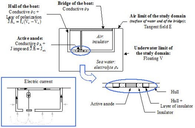
In this example a cathodic protection of a boat by means of an active anode and of a reactive anode (sacrificial) is presented.
The treatment of the problem in simplified or incomplete computation mode (without taking into account the current density in the metal structure) is represented in the figure below.
The boat is represented using face regions (known as immaterial), which allows imposing boundary conditions.
Example (2)
It deals with the same example as in the previous block.
The treatment of the problem in complete computation mode (with the taking into account of the current density in the metallic structure) is represented in the figure below.
The boat is represented using face regions (known as material) that allow the modeling of thin conducting or insulating regions. Boundary conditions are also applied at the level of these face regions.
