Since version 2026, Flux 3D and Flux PEEC are no longer available.
Please use SimLab to create a new 3D project or to import an existing Flux 3D project.
Please use SimLab to create a new PEEC project (not possible to import an existing Flux PEEC project).
/!\ Documentation updates are in progress – some mentions of 3D may still appear.
Flux-Simulink co-simulation: Preparation of the Simulink model
Introduction
Now that the preparation for the Flux project has been done, the preparation of the Simulink model can be carried out.
Upon the opening of Matlab Simulink via the Flux supervisor (compulsorily), the new library « Coupling with Flux » is added to the Simulink library.
The user must prepare the Simulink model by adding and characterizing the coupling library and equally the necessary libraries for the construction of the desired model.
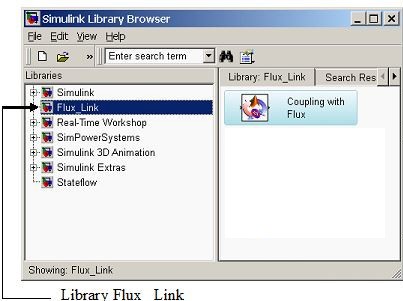
Simulink library
The new library of Flux – Matlab Simulink coupling is added to the list of old libraries listed for the historical Flux2D.
The next figure shows the location of the new library added in the Simulink library.
| Element | Function |
|---|---|
| Librairie Flux_Link | Library that contains the Flux – Matlab Simulink couplings. This library is automatically accessible with Simulink Library Browser only if the opening of the Matlab Simulink has been made through the Simulink link in the Flux supervisor. |
| Coupling Block |
Permits the coupling between Flux and Simulink. This section is compatible with Flux2D and Flux3D on the 64 Bits system. |
« Coupling with Flux » block
The new block «Coupling with Flux» available in Simulink has several properties which are classified in different tabs:
- Project
- Solver
- Application
- Memory
The content of each of these tabs is detailed in the following sections.
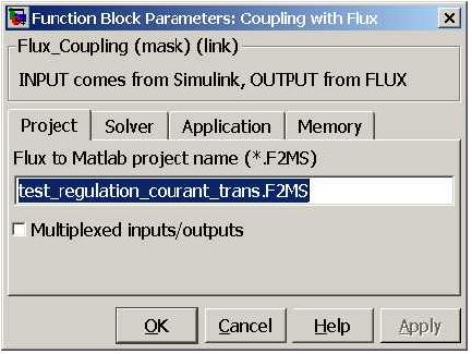
« Project » tab
Here is the content of the «Project» tab:
| Element | Function |
|---|---|
| Flux to Matlab project name (*.F2MS) |
Permits the user to fill in the name of the project *.F2MS (Flux to Matlab Simulink) that is the same as the Flux project name to ensure successful coupling between the two software. Attention to correctly enter the extension .F2MS |
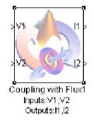
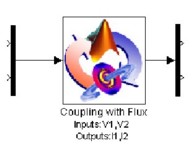
| Multiplexed inputs/outputs |
Permits the user to choose the representation of the inputs/outputs:
|
| Individual input/output blocks | Vector Input/Output blocks |
|---|---|
|
|
« Solver » tab
Here are the contents of the «Solver» tab:
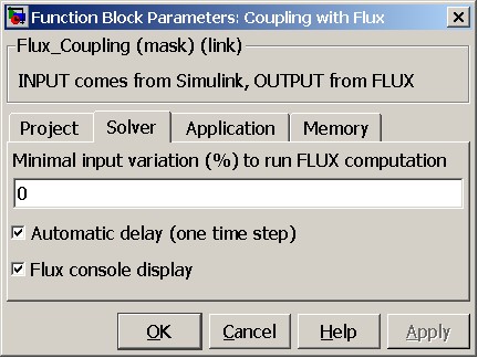
| Element | Function |
|---|---|
| Minimal input variation (%) to run FLUX computation | Permits to define a percentage of variation of the input parameters between two calculation steps under which the Flux calculation will not be carried out. What matters is to be able to carry out several Simulink time steps, without systematically carrying out a Flux calculation. |
| Automatic delay (one time step) |
Permits to Flux to calculate the output parameters with a delay of one step and to transmit them to Simulink for the calculation of the following step. This automatic delay mode is indispensable in case of retro-action between output and input to avoid the algebraic loops. However, if there is no retro-action, the automatic delay should not be activated, as this would imply a delay of one step upon the output parameters. |
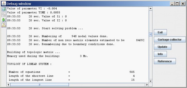
| Flux console display | Permits to display a supplementary window where Flux actions are entered. This is the equivalent of the Historical zone visible in Flux, zone placed below the geometric view. |
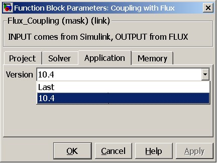
« Application » tab
Here are the contents of the « Application » tab:
| Element | Function |
|---|---|
| Version |
Permits to choose the Flux version to be coupled with Simulink during the solving process. The user has a choice between:
|
The same for the static initialization. It is activated or not in the Flux project upon defining the application.
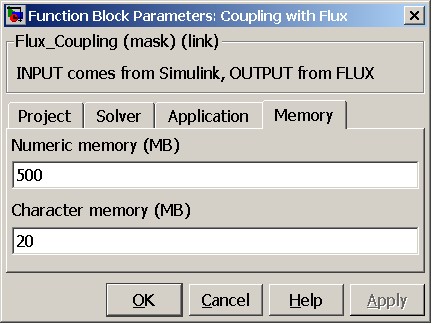
« Memory » tab
Here contents of the « Memory » tab:
| Element | Function |
|---|---|
|
Numeric memory |
Permits to define the numeric memory allocated for
Flux Note: The value "0" allows to launch Flux in dynamic
memory |
| Character memory | Permits to define the character memory allocated for
Flux Note: The value "0" allows to launch Flux in dynamic
memory |
Configuration of simulation parameters
The configuration of the simulation parameters is done only via Simulink, in the menu