Since version 2026, Flux 3D and Flux PEEC are no longer available.
Please use SimLab to create a new 3D project or to import an existing Flux 3D project.
Please use SimLab to create a new PEEC project (not possible to import an existing Flux PEEC project).
/!\ Documentation updates are in progress – some mentions of 3D may still appear.
Flux-Simulink co-simulation: Example
Introduction
To permit to the user to implement the co-simulation between Flux and Matlab-Simulink, a detailed example, with the main stages to be implemented, is given in the following sections.
Example description
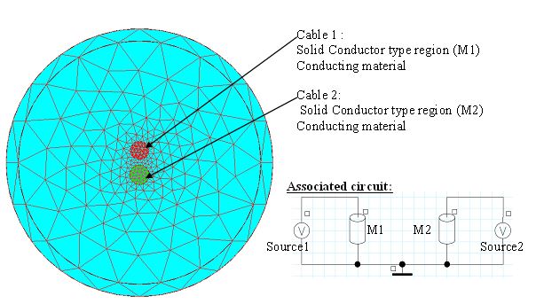
The example represents two cables, one supplied with sinusoidal voltage, the other with triangular voltage.
If the cables are placed close enough, there will be a electromagnetic influence of one upon the other, and the currents will not be perfectly sinusoidal or triangular, respectively.
Therefore, the purpose of the study is to regulate the current in the cable supplied with sinusoidal voltage to obtain a sinusoidal current.
Flux project
The geometry, mesh and physics are given below.
Preparation of I/O parameters in Flux
The input and output parameters are described as follows :
| I/O | name | Description | Type | Value / formula |
|---|---|---|---|---|
| Input parameters | V1 |
Supply voltage of the cable 1 associated to the voltage source Source1 |
I/O parameter, multiphysics |
Reference value =0 |
| V2 |
Supply voltage of the cable 2 associated to the voltage source Source2 |
I/O parameter, multiphysics |
Reference value = 0 | |
| Output parameters | I1 |
Current in the cable 1 (current in the solid conductor M1 ) |
I/O parameter defined by a space formula | I(M1) |
| I2 |
Current in the cable 2 (current in the solid conductor M2 ) |
I/O parameter defined by a space formula | I(M1) |
Generation of component in Flux
To generate the component of the Flux – Matlab Simulink coupling:
| Step | Action |
|---|---|
| 1 |
Open the dialogue box:
|
| 2 | Define the name of component ( for example CABLES) |
| 3 |
Choose the input parameters:
|
| 4 |
Choose the output parameters:
|
| 5 | Validate by clicking on OK |
| → |
A CABLES.F2MS file has been created. The Flux project has been duplicated and registered under the name: CABLESF2MS.FLU |
Preparation of the Simulink model
To prepare the Simulink model:
| Step | Action |
|---|---|
| 1 |
Open Matlab:
|
| 2 | Open Simulink by clicking on |
| → | The Simulink library is open. |
| 3 |
Make a new model :
|
| → | A blank window will appear |
| 4 |
Register the model:
|
| 5 |
Place the section « Coupling with Flux »
|
| 6 |
Characterize the section « Coupling with Flux »:
|
| 7 | Place, characterize and connect the other necessary libraries according to the model in the figure below. |
| 8 | Save the model by clicking on Save in the menu File |
| → | The preparation of the Simulink model is complete |
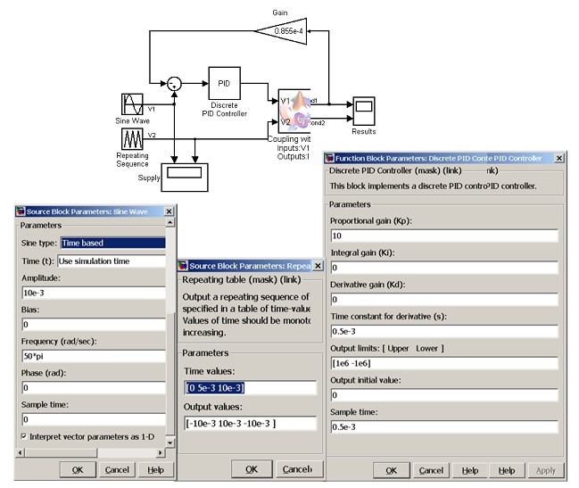
Configuration simulation
Configure the simulation parameters with a time interval from 0 to 0.6 s and the time step set at 0.001 s and launches the solving process.
During the solving process the actions carried out in Flux are visible in the Flux console, which has appeared in a new window, and the information on the solved steps are also displayed in the window " Command Window" of Matlab.
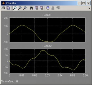
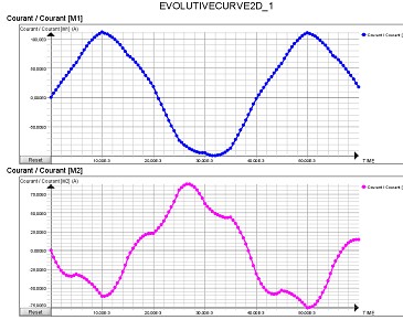
Analysis of results
The results can be analyzed in Matlab – Simulink, as well as from Flux in the project CABLESF2MS_SOLVED.FLU
| Graph results in Matlab-Simulink | Graph results in Flux |
|---|---|
|
|