Constructing the Spiral Antenna
Create the complementary slotted two-arm spiral antenna in CADFEKO.
- Set the model unit to centimetres.
-
Create the following variables:
- a = 1.1459 (The spiral growth ratio.)
- r1 = 1 (The base radius of the spiral.)
- r2 = 45/2 (The end radius of the spiral.)
- w = 1.8 (The width of the slot.)
- width = 70 (The width and depth of the conducting plate.)
- n1 = r1/(2 * pi * a)
- n2 = r2/(2 * pi * a)
- n = n2 - n1 (The number of turns.)
- fmin = 150e6 (The minimum frequency.)
- fmax = 900e6 (The maximum frequency.)
- lambda0 = 100 * c0/fmax (A scale factor of 100 to compensate for working in centimetres.)
- meshing = min(lambda0/12, 1.3 * w) (The triangle length to be minimum of or .)
-
Create a helix.
- Definition method: Base centre, base radius, end radius, height, turns
- Origin of the helix (C): (0, 0, 0)
- Base radius (Rb): r1
- End radius (Rt): r2
- Height: 0
- Turns (N): n
- Label: Helix1
Figure 1. Top view of Helix1. 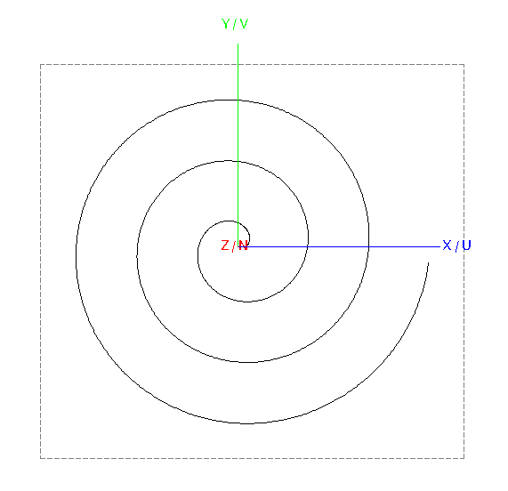
-
To add width to the spiral, create a copy (duplicate) of
Helix1.
-
Modify the start radius and end radius:
- Base radius (Rb): r1 + w
- End radius (Rt): r2 + w
Figure 2. Top view of Helix1 and Helix2. 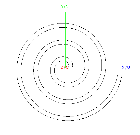
-
Modify the start radius and end radius:
-
Connect the two helices to create a surface (loft).
-
Select Helix1 and Helix2 and loft
the two curves to create a surface.
Note: Do not select the Reverse orientation check box.
Figure 3. Top view of the lofted surface (spiral). 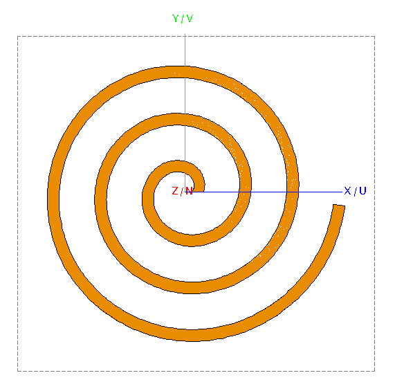
-
Select Helix1 and Helix2 and loft
the two curves to create a surface.
-
Create half of the feed.
-
Create a polygon.
- Corner 1: (r1 + w/2, -w/2, 0)
- Corner 2: (0, -w/2, 0)
- Corner 3: (0, w/2, 0)
- Corner 4: (r1 + w/2, w/2, 0)
- Corner5: (r1 + w, 0, 0)
- Label: Polygon1
Figure 4. Top view of the lofted surface (spiral) showing half of the feed at the centre. 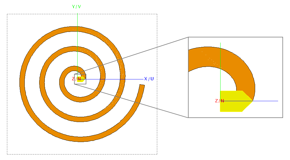
-
Create a polygon.
- To ensure mesh connectivity between the feed and helix, union the lofted surface (Loft1) and the feed (Polygon1). The default label for the new union is Union1.
- Simplify Union1 to remove non-essential edges and faces.
-
Create the second arm of the spiral antenna.
-
Copy and rotate Union1 by 180° around the N axis.
Figure 5. Top view of the two-arm spiral. 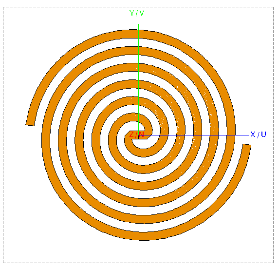
-
Copy and rotate Union1 by 180° around the N axis.
- Union all parts of the model. Rename the union to Union2.
-
Create the conductive plate which will contain the complementary slotted spiral
antenna.
-
Create the spiral slots in the conductive plate.
-
Subtract Union2 from
Rectangle1.
Figure 6. Top view of the two-arm spiral slots in a conductive plate. 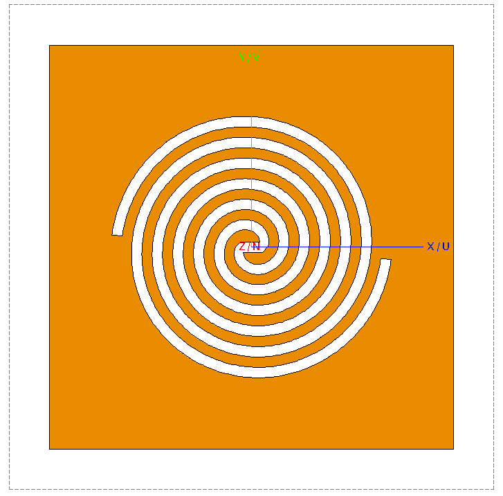
-
Subtract Union2 from
Rectangle1.
-
Create the feed wire.
-
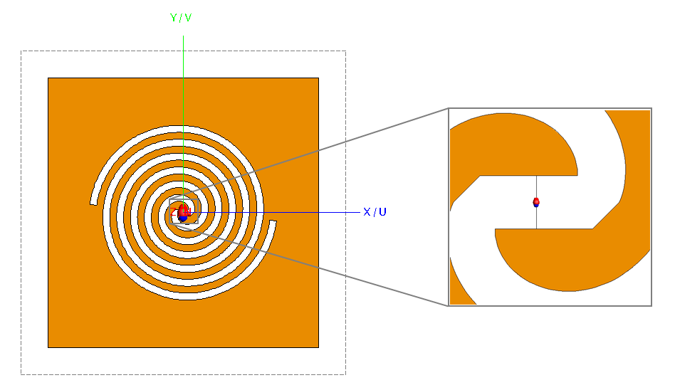
Add a wire port to the feed wire.
Figure 7. Top view of the complementary two-arm slot antenna showing the wire port at the feed line.