How to Interpret Far Fields Calculated from a PBC
Solution
This How-To helps to interpret far-fields (total and scattered) calculated with the
periodic boundary condition (PBC) solution.
For the PBC solution, the default far field is calculated from the solution of a single
unit cell radiating in free space. The PBC unit cell solution is obtained for an
infinite array, meaning all the array element currents/fields are the same.
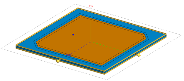
For a PBC unit cell, consider a truncated patch (derived from the component library) that
radiates left-hand circular (LHC) polarisation.Figure 1. The truncated patch PBC unit cell geometry.
Consider two cases:
The PBC patch is exited with a voltage source with a specified beam pointing
angle.
The PBC patch is excited with a plane wave, and the port is loaded with 50
Ohm.
Voltage Source Excitation
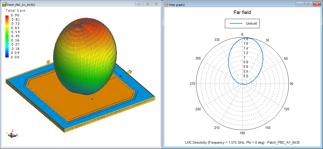
The PBC solution is obtained by exciting the patch with a voltage to have a beam
pointing angle {theta, phi} = {30, 0} degrees.
Note: The unit cell beam will not
necessarily point to the beam pointing angle.
Figure 2. The LHC far field directivity pattern of the unit cell.
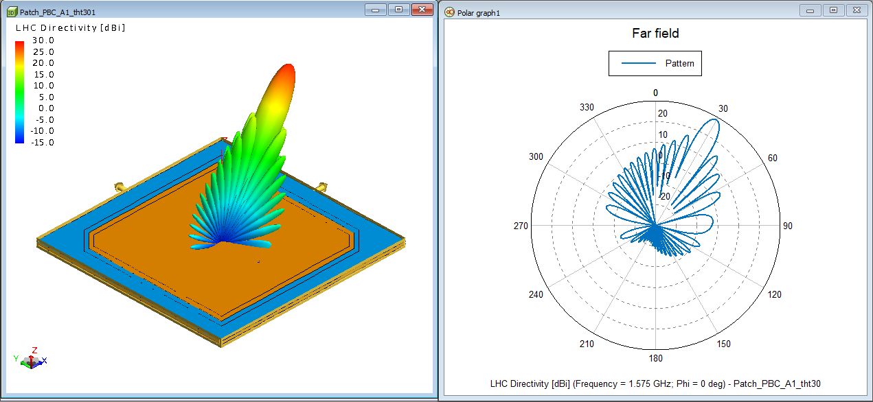
It is only when requesting the far field1 for a large finite array that the beam pattern will align with
the specified pointing angle.Figure 3. The LHC far field directivity of a 21x21 element array excited uniformly.
Only the unit cell geometry is displayed in the 3D view.
Plane Wave Excitation
The PBC solution is obtained for two sets of incident plane waves: one with left-hand
circular polarisation (LHC) and another with right-hand circular (RHC) polarisation.
Request the bi-static far field for the unit cell (default) and a 21x21 element
array.
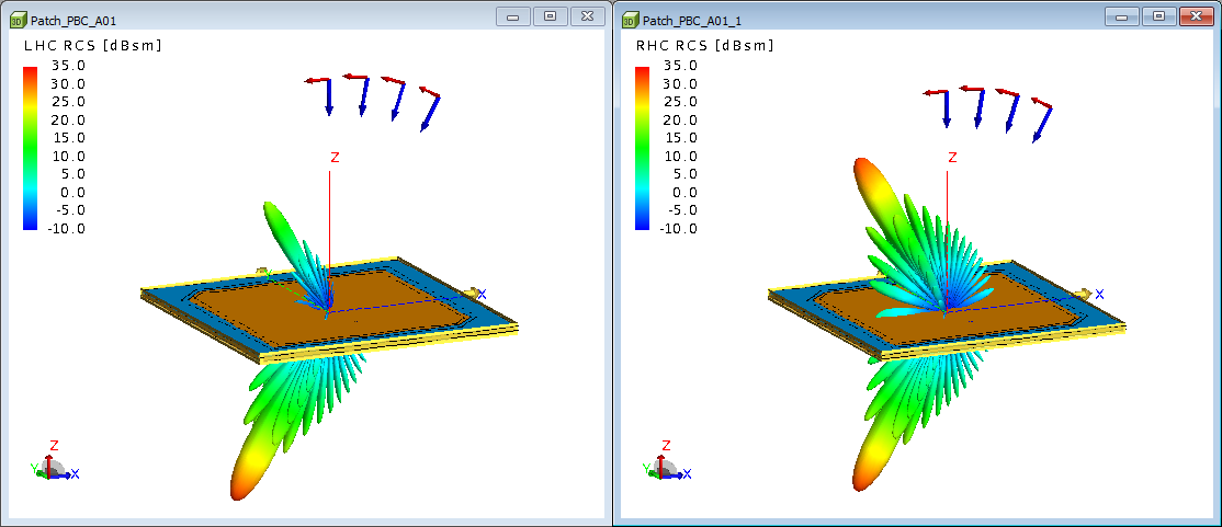
Figure 4 shows the bi-static
RCS pattern for a 21x21 array. Figure 4. The co-polarised bi-static RCS for the 21x21 array with incident angle
(theta_i, phi_i} = {30, 0}. Left: LHC polarised plane wave; Right: RHC
polarised plane wave. Again, only the unit cell geometry is displayed in the 3D view. The bi-static
RCS includes only the scattered field from the array. It cannot include the
plane-wave field contribution as the plane-wave E-field does not decay with 1/r.
This is the reason for the large forward scatter beam below the array. A large
forward scatter beam is needed to cancel the incident field.
The total near field, which includes the plane wave field contribution, below the
unit cell will be zero. Numerically it will have some finite (but insignificant
small) level due to the discrete nature of the current solution, typically >40 dB
below the incident field level.
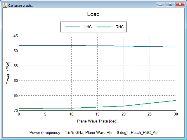
The patch array reflects less power when the incident polarisation is matched (LHC),
compared to when the incident polarisation is mismatched (RHC).
This is consistent with the received power in the 50 Ohm load versus incident angle
for LHC and RHC incident polarisation.Figure 5. The co-polarised bi-static RCS for the 21x21 array with incident angle
(theta_i, phi_i} = {30, 0}. Left: LHC polarised plane wave; Right: RHC
polarised plane wave. More power is received when the incident polarisation (LHC) is matched to
pattern polarisation (LHC) when the patch is excited.
1 Some advanced options are available on
the Request Far Fields dialog
(Advanced tab): option to calculate the far field
from a finite array instead of one unit cell; option to calculate the scattered
field only.