Constructing a Feed for the GCPW
Create the feed elements for the edge ports.
-
At each end of the signal conductor, create a connecting rectangle. These two
rectangle faces are used when defining the edge ports.
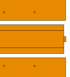
Figure 1. Top view of the GCPW showing the connecting rectangle at the end of the signal conductor. Note that the ground plane is hidden.Note: Keep the width of the connecting rectangles less than to prevent higher order modes or resonances over the width of the feeding edge. -
At each end of the signal conductor, create a vertical plate that connects to
the ground plane.
The vertical plates at the end of the line mimics the surface of a connector that would need to connect to the lines as well as the ground plane.
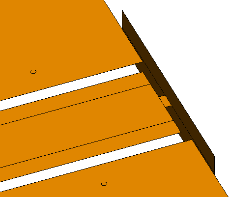
Figure 2. Isometric view of the GCPW showing the vertical plate. Note that the ground plane is hidden. -
At each end of the signal conductor, add an edge port at the edge between the
connecting rectangles and the vertical plate.

Figure 3. An isometric view of the GCPW showing the edge port. Note that the ground plane is hidden.