Constructing a Conformal Patch Antenna
Create the conformal patch antenna in CADFEKO.
- Set the model unit to millimetres.
-
Add a work plane.
- Origin: (0, 0, -40)
- V vector: (0, 0, 1)
- Label: workplane_hors
-
Set the workplane_hors as the default workplane.
Tip: Expand Workplanes in the tree, open the right-click context menu and click Set as default.
-
Create a cylinder.
- Definition method: Base centre, radius, height
- Base centre (B): (0, 0, -40)
- Radius (R): 40
- Height (H): 80
- Label: cylinder_out
-
Create a copy (duplicate) of the cylinder_out part and
modify the following:
- Radius (R): 40 - 2.87
- Label: cylinder_in
-
Subtract cylinder_in from
cylinder_out.
Figure 1. Remaining geometry after subtracting the two cylinders. 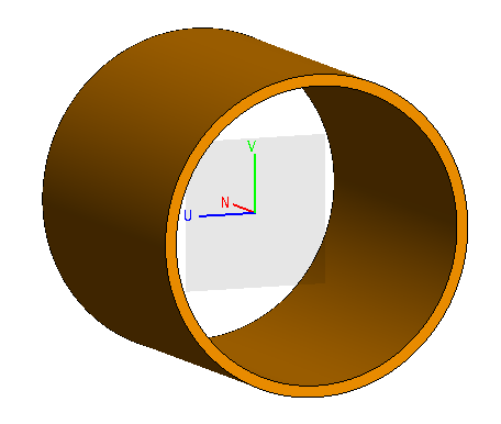
-
Define the following variables:
- alpha = deg(50/40)
- beta = deg(31.1807/40)
-
Split the Subtract1 part:
- Plane: UN
- Rotate split plane, N axis: 90 - alpha/2
This creates two parts, Split_front1 and Split_back1. - Delete the Split_back1 part.
-
Split the Split_front1 part.
- Plane: UN
- Rotate split plane, N axis: 90 + alpha/2
This operation results in two parts, Split_back1 and Split_front1. -
Delete the Split_front1 part.
Figure 2. The finite solid outline of the patch antenna with correct dimensions and curvature, but with no material, face properties, or feed. 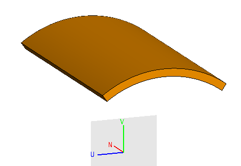
-
Create the leading edge of the patch.
- Rotate the edge_of_patch part on the N axis through an angle of -beta/2 degrees.
-
Spin the edge_of_patch part on the N axis through an
angle of beta degrees.
Figure 3. View after spinning the leading edge in the previous step. 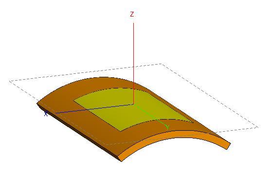
-
Create the patch antenna feed.
-
Position the feed line at the exact feed position.
- Rotate the feed part through an angle of -beta/2 + deg(8.9/40).
Figure 4. View of the patch antenna showing the feed line in yellow. 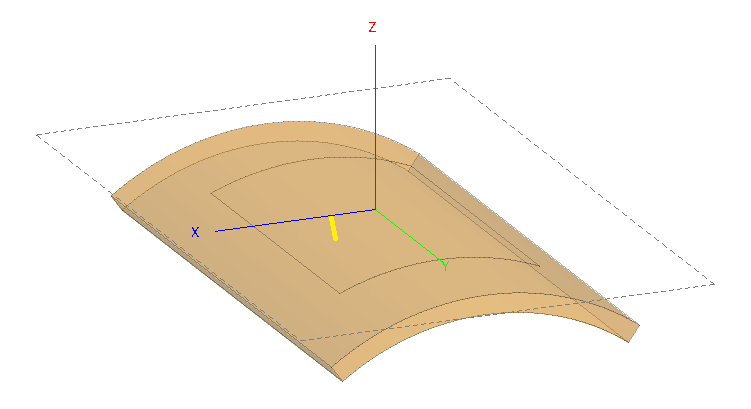
Tip: Use one of the following methods to view the feed inside the model: Change the opacity of the model or use a cutplane. - Union all the parts.
-
Create a dielectric medium.
- Relative permittivity: 2.2
- Label: substrate
- Set the region of Union1 to substrate.
- Set the bottom face of Union1 to perfect electric conductor.
- Set the top face of Union1, which corresponds to the metallic patch, to perfect electric conductor.
-
Create a Wire port on the feed line.
Tip: Use a cutplane to add the wire port.
- Create a Voltage source on Port1 with default settings.
- Set the Frequency to 3e9 Hz.
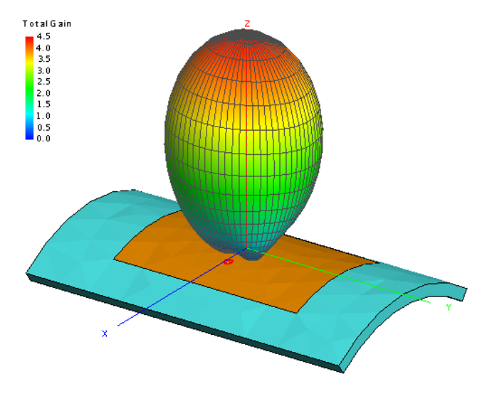
- Create a full 3D far field request. Set the workplane (for this request) to the Global XY workplane.
-
Create the mesh.
- Mesh size: Standard
- Wire segment radius: 0.65
Note: If the meshing process takes more than two seconds, you may have neglected to set the Model unit. Change the Model unit to Millimetres (mm) and remesh the model.Figure 5. View of the 3D pattern in POSTFEKO.