Release Notes: Altair Feko 2023.1
Altair Feko 2023.1 is available with an assortment of new features, corrections and improvements. Altair Feko 2023.1 is a major release. It can be installed alongside other instances of Altair Feko.
Feko is a powerful and comprehensive 3D simulation package intended for the analysis of a wide range of electromagnetic radiation and scattering problems. Applications include antenna design, antenna placement, microstrip antennas and circuits, dielectric media, scattering analysis, electromagnetic compatibility studies including cable harness modelling and many more.
newFASANT complements Altair’s high frequency electromagnetic software tool (Altair Feko) for general 3D EM field calculations, including, among others, special design tools tailored for specific applications like complex radomes including FSS, automated design of reflectarrays and ultra-conformed reflector antennas, analysis of Doppler effects, ultrasound systems including automotive or complex RCS, and antenna placement problems. Advanced solver technologies like the MoM combined with the characteristic basis functions (CBFS), PO/GO/PTD, GTD/PO and MLFMM parallelised through MPI/OpenMP, being some of them especially efficient for the analysis of electrically very large problems.
WinProp is the most complete suite of tools in the domain of wireless propagation and radio network planning. With applications ranging from satellite to terrestrial, from rural via urban to indoor radio links, WinProp’s innovative wave propagation models combine accuracy with short computation times.
WRAP is a comprehensive tool for electromagnetic propagation, antenna collocation and spectrum management. WRAP combines propagation analysis, often over large areas with many transmitters and receivers, with system analysis to include complex non-linear equipment properties.
Highlights of the 2023.1 Release
The most notable extensions and improvements to Feko, newFASANT, WinProp and WRAP in the 2023.1 release.
Salient Features in Feko
- Feko's combined MoM/MTL cable solution method is extended so that the
outermost shield signals of different paths in the harness may be connected to each other
through a closed shielded conducting enclosure of arbitrary shape defined in the 3D full
wave model. Full coupling is considered between the cable harness, the shielded enclosure
and the environment. Non-radiating electrical and circuit connections between different
cable path signals can be defined in a schematic view - effectively modelling connections
and circuitry within the shielded enclosure.
Figure 1. Illustration of the new shielded enclosure functionality in Feko. 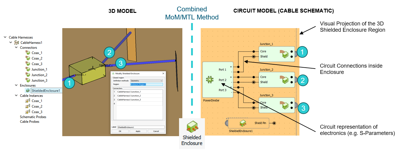
- The following components were added to the component library:
- A generic car model
- A
shark fin
antenna system for cellular, GNSS, SDARS, V2X and WLAN, typical in automotive applications - A generic windmill model
Figure 2. Three new components available in the Feko 2023.1 component library. 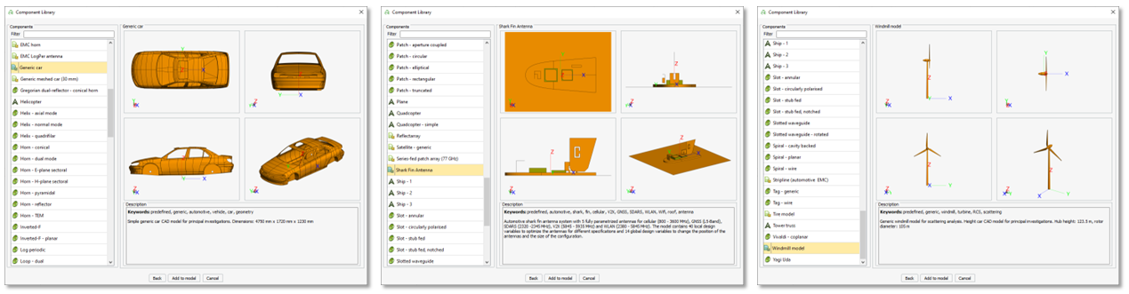
Salient Features in WinProp
- ProMan now supports 5G beam switching capability using a
predefined set of beams. Users can now be served by a dedicated beam, with the possibility
to transition to a different beam as they move.
Figure 3. Left: Only the data beams that are serving a user are active (the best serving beam is selected. Centre: If the user moves, it switches to another predefined beam. Right: The serving beam is not necessarily oriented in the direct direction, it can for example, come from a reflection at the building. 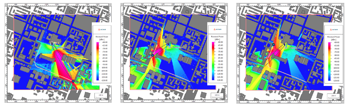
- Added support in ProMan to display the total power from
all transmitters in the tree under Results: Propagation if the
Superposed Received Power check box was selected.
Figure 4. The total power is available in the tree if the option was enabled. 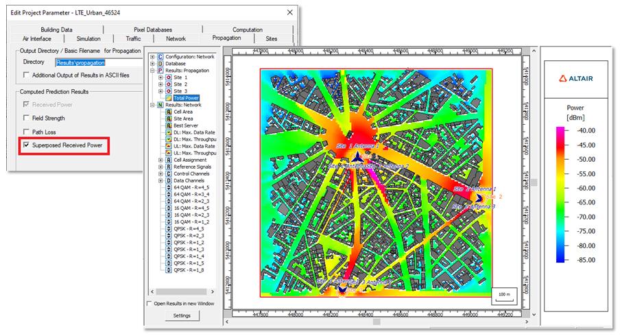
- ProMan was extended to define and display reference points
on maps. These points are always visible on a map using an
X
sign (even if data is plotted). The names of points (prediction, user or reference points) can now be shown or hidden using the setting on the Display Settings dialog.Figure 5. Reference points can be added to a map. 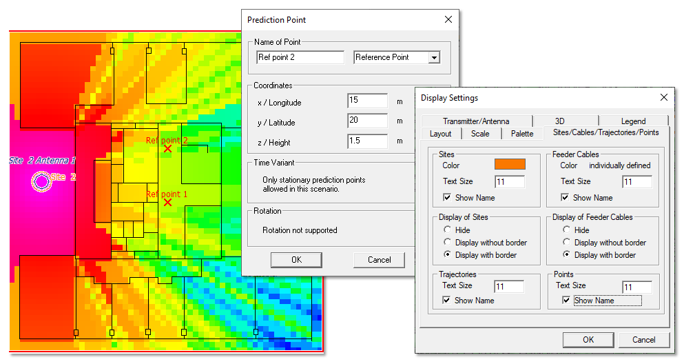
Salient Features in WRAP
- The ITU-R P.1812 propagation model was updated to recommendation ITU-R P.1812-6.
- The Clutter Loss Model was updated to recommendation ITU-R P.2108-1.
- Support was added to enter 5G parameters for calculations. The 5G parameters are used when calculating RSRP, RSSI, RSRQ, SINR, Data rate and Throughput.
Feko 2023.1 Release Notes
The most notable extensions and improvements to Feko are listed by component.
CADFEKO
Features
- Added functionality to reference grouped variables via their group name. Before it was required to give variables unique labels to ensure referencing the correct variable. It is now possible to distinguish between variables inside different groups and ungrouped variables, for example, Var1, Group1.Var1 and Group2.Var1.
- Added the option to specify the transmit power to be used during the S-parameter calculation.
- Added the Ensure continuous region representation option to the Advanced tab of the Voxel Mesh Settings dialog. This setting controls whether a voxel mesh representation is created for a thin dielectric region which does not cut across multiple voxels.
- Extended cable schematics to support a distinction in concepts between local circuit device ground and global installation ground. This is achieved through the addition of new symbols for
Device ground
andInstallation ground
. - The ECAD import library used by CADFEKO, has been upgraded to the latest version provided by Altair PollEx.
- Gerber files (274X or 274D format) can be imported.
- Meshes can be exported to the Gerber file format.
- Feko's combined MoM/MTL cable solution method was extended to allow for the outermost shield signal of different paths in the harness to be connected via a shielded conductive enclosure defined in the full wave model. Inner circuit connections between different cable path signals bounded by the enclosure are now supported. Full coupling is supported between the cable harness, enclosure and the environment.
- Added the Show mesh configuration details checkbox to the advanced tab of the Modify Mesh Settings dialog. This option, when enabled, reveals some of the calculated values used for meshing.
- Improved the display of selected items (geometry and mesh parts and entities) in the 3D view.
- Added new visibility options. Show and Hide are available in addition to the existing visibility options such as toggling the visibility. All visibility options are grouped together inside the Visibility sub-menu on the right-click context menu.
- Changes were made to colours used in the 3D view to aid model investigation. Edges and wires are now shown in a thicker blue instead of yellow from previous versions. Various styling improvements were made to make it easier to work with and find items in the 3D view.
- Improved the display of selected items to be opaque when using opacity. This highlights the selected item with the rest of the model being semi-transparent. The overlay is also automatically hidden when opacity is used, resulting in a cleaner and clearer display of the model.
- Added a generic windmill model to the component library.
- Added a generic car CAD model to the component library.
- Extended the model tree to indicate hidden items with grey text and a disabled first icon. If an item is not visible, but sub-items are visible, the icon is updated to indicate the partial visibility. For excluded items, all icons are disabled.
- Extended the PCB import dialog with a netlist filter that enables to the user to specify specific nets to be imported.
- Added checks to ensure that schematic circuit connections take preference over mesh connections in combined MoM/MTL cable harnesses.
- Added the option to Preserve all entities for global and local mesh settings. This option is used to retain an entity after meshing. Tiny edges in the model, that would otherwise be collapsed, can be retained by enabling this option.
- Updated the layout of the S-parameters dialog.
- Added an additional Simplify option to the Spin operator. With this option enabled, redundant vertices and edges are removed as a final step in the creation of the spun geometry. This simplification was performed by default when creating spun geometry in the original 2023 release, but had to be removed since it was not available in CADFEKO [LEGACY] and caused issues for the conversion of legacy models.
- Added a model of a parameterised automotive shark fin antenna system (Cellular, GNSS, SDARS, V2X, WLAN) to the component library.
Resolved Issues
- Fixed a crash when pressing the delete button twice in quick succession to delete geometry entities such as edges or faces.
- Improved usability by reviewing and updating visibility and visualisation features.
- Fixed a bug where replacing parts in sub-trees did not perform the correct mapping. The incorrect mapping could result in strange behaviour such as Show All having no effect on the items.
- Corrected an issue with the cable schematic view where the view resized and connectors were placed on top of each other when adding a cable connector.
- New CADFEKO now theoretically supports saving and loading model file sizes up to 9 Exabytes. Previous models were limited to a maximum of 2 Gigabytes or less, depending on model complexity.
- Resolved an issue that prevented importing a CADFEKO model containing references to variables inside groups and using a prefix during import. Depending on the version, either a Variable not found error was issued or an assertion failed when attempting to import a model with grouped variables.
- Resolved an assertion failure when the user interacts with the 3D view after switching off automeshing.
- Various improvements in meshing of models that failed to mesh.
- Resolved an issue with the schematic view not opening with the same view (zoom level and position) as at the time of saving the model.
- Resolved an issue with a sudden change in the schematic view after loading a model and panning or zooming the schematic view.
- Improved mapping of edges when using the sweep and the path sweep operator or any operation that derives entities from other entity types (a vertex being the source of an edge or an edge being the source of a face or a face being the source of a region). This change causes edges to have different labels, but is an improvement (correction).
- Fixed a problem where a rendering update box would always be displayed in the preview for a split operation.
- Resolved an issue where grouped variables did not show on the Modify variables dialog. Variables inside groups can now be modified on this dialog and variables can be moved between existing variable groups.
- Fixed a bug that caused some models to hang during legacy conversion.
- Improved meshing of tightly coiled helix structures when using the new default mesher in CADFEKO. Invalid meshes may still be encountered when switching to the legacy mesher or when using CADFEKO [LEGACY].
- Fixed the loading performance of models where a large number of model verification warning or error messages get issued.
- Resolved a crash that could be encountered when working with a model containing cable ports that are not associated with a cable harness. It was possible to create a model like this in older versions of CADFEKO where cable ports were not deleted when the cable harness that they referenced was deleted. Any cable ports that are not associated with a cable harness are now deleted from a model when it gets loaded.
- Improved internal CAD model structures to reduce memory usage and file size and to improve performance.
- Added verification that an edge mesh port cannot bound a FEM region.
- Resolved an issue with the Show/Hide functionality where showing a port on hidden geometry resulted in all other geometry being hidden in the 3D view.
EDITFEKO
Features
- Added the schematic link (SL) card for defining the interface between cable schematic elements and 3D geometry.
- Added an option to the SP card to specify the transmit power to be used during S-parameter calculation.
- Updated text on the AK, CI and LC cards to distinguish between device ground and installation ground pins.
- Added a new cable harness (CH) card to group harness specific parameters.
- Extended the CS card to allow for the definition of a connection to the device ground at the start or end of a cable path section in combined MoM/MTL cable harnesses.
POSTFEKO
Resolved Issue
- Corrected the positioning and sizing of graphs with PDF report generation.
Solver
Features
- Upgraded Qt and OpenSSL to the latest versions.
- Support S-parameter calculations at a user-defined transmit power level.
- Updated Intel MKL to version 2023.2.
- CMA support for generalised impedance boundary conditions (GIBC) applied on the boundaries of SEP regions.
- Improved accuracy of the characteristic mode analysis for impedance boundaries in the free space, port loads and networks.
- Added support for CMA simulations with the CFIE.
- Added support double edge and wedge diffraction with Faceted UTD. Ray paths between sources and observers can now concatenate two single diffractions at physical edges and wedges. Consideration of this effect requires "Edge and wedge diffraction" and "Higher-order effects" to be enabled and a maximum number of interactions larger than or equal to two.
- Significantly increased faceted UTD simulation speed over discrete frequency bands by reusing calculated rays.
- Support Physical Optics integration to compute the radiation from equivalent sources using RL-GO with high accuracy setting. It improves the accuracy of the solver by considering the phase variation of the equivalent current across the ray footprints on the geometry.
- Reduce the memory footprint for the parallel MPI direct sparse FEM solver of more than hundred thousand unknowns by using some MPI processes as threads during the sparse LU factorization and solve phases.
- The combined MoM/MTL method was extended to support additional configurations when connecting cable path end points and the MoM mesh. As an example, pigtail-type connections can now be accurately represented. Configuring these connections is not trivial, and this will be addressed in future updates.
- Upgraded MUMPS to version 5.6.2altair.
- The performance of hybrid FEM/MoM simulations involving multiple excitations (for example a solution with plane-wave incidence angles or a multiport S-Parameter calculation) is improved by avoiding re-computation of matrices where it is not neccessary.
- The MTL solution method was extended to support a distinction in concepts local circuit device ground and global installation ground. Circuit connections between harness signals and a nearby local device ground is considered non-radiating. The net current through elements connected between the device ground and the installation will be added as impressed currents to the radiating solution. For combined MoM/MTL harnesses the device ground indicates the transitioning point from circuit to full wave solver. Connections beyond the device ground should be included in the full wave model.
- Accelerated loss calculations over segments, triangles, VEP cuboids and VEP tetrahedra by parallelizing the relevant routines.
- Improved the speed of computation of spherical modes for multi-processor simulations.
- Improved parallel process memory scaling when using the direct FEM sparse solver for a hybrid FEM/MoM solution.
Resolved Issues
- Implemented validation for model mesh labels to ensure compatibility with solvers.
- In combined MoM/MTL harnesses schematic circuit connections now take preference over mesh connections. This results in the setup of an improved full wave model.
- Resolved a bug in no results being computed in standard configurations defined after a CMA configuration.
- Improved the management of far-field interactions for MLFMM algorithm for models with very high losses to avoid errors during the iterative solution.
- Corrected excessive memory consumption and potential crash when running large ACA simulations over multiple nodes.
- Avoid internal error 32488 when using both CFIE and EFIE in a solution involving CBFM and MLFMM.
- Corrected errors with adaptive cross-approximation (ACA) solutions including multilayer planar dielectrics and using threads.
Shared Interface Changes
Support Components
Features
- The CADFEKO [LEGACY] graphical user interface component is in the process of being phased out and is no longer included in the main Feko installation. It is available as a separate installation for users who need to continue using the CADFEKO [LEGACY] graphical user interface while the new interface gets rounded off based on feedback received.
- Removed the functionality to launch CADFEKO [LEGACY] from the Launcher utility. The CADFEKO [LEGACY] interface can still be installed alongside the Feko installation and launched directly from the installed location.
- Added the Create Edge Port for Finite Substrate macro that creates an edge port on a finite substrate. The macro removes a small cuboidal section and creates a PEC
bow-tie
structure. An edge port is then added to the centre edge of thebow-tie
structure. This macro simplifies the process of adding an edge port to a finite substrate since a port cannot be placed on the boundary of a finite dielectric substrate when using the method of moments (MoM).
WinProp 2023.1 Release Notes
The most notable extensions and improvements to WinProp are listed by component.
General
Feature
- Updated Intel MKL to version 2023.2.
ProMan
Features
- Added support to specify and display reference points on maps. The points are defined on the Prediction Point dialog and are always visible on a map (even if data is plotted) using an
X
sign. Added support to show/hide the names of points (for example, prediction, user or reference points) on the Display Settings dialog. - Improved the loading time of predictions in the vertical plane.
- Added support for 5G beam switching capability using a predefined set of beams. Users can now be served by a dedicated beam, with the possibility to transition to a different beam as they move.
- Extended urban empirical models to include ray intersections with vegetation.
- Changed the minimum reflection angle to 0.1 deg, before it was 1 deg.
- The total power from all transmitters together can now be displayed (optional) after a regular propagation simulation.
Resolved Issues
- Resolved an issue for the SBR/SRT where rays were incorrectly discarded while checking for line-of-sight.
- Resolved an issue for the SBR where rays were discarded due to incorrect path loss estimation.
- Fixed a problem where the transmission loss was computed incorrectly for empirical losses.
newFASANT 2023.1 Release Notes
The most notable extensions and improvements to newFASANT are listed by component.
GUI
Resolved Issues
- Various improvements have been made to the image rendering and the shading of the 3D view has been adjusted.
Solver
Feature
- Updated Intel MKL to version 2023.2.
WRAP 2023.1 Release Notes
The most notable extensions and improvements to WRAP are listed by component.
General
Features
- Updated WRAP equipment databases to version 173.
- Moved the import and export to the same menu as other area formats.
- WRAP will not open API sockets by default. The user needs a valid API license and the license feature SolverHPC and OpenAPISocket element should be enabled in the WRAP settings file WRAPSettings.ini.
- Altair license feature
SolverHPC
is required to use Socket communication API functionality in WRAP. - A new function was added in ObsMan to allow the exclusion of existing cases from calculations.
- The colour of the obstacles shown in the map are now different depending upon the obstacle origin and status.
- Added the option to limit the number of created wind turbines in an ObsMan wind turbine farm.
- Added ability to show obstacles from FIA and ObsMan simultaneously. Shown obstacles stays with their selection per ObsMan tab page.
- Made the following dialogs resizable in map viewer: Open Area dialog and Delete Area dialog. Made the following dialogs resizable in Obstruction Manager: main window, Select case dialog, Method 2 settings dialog, Detailed Calculation Results dialog, Detailed link result dialog, Radar types dialog and Create obstacle farm dialog.
- Propagation model ITU-R P.1812 has been updated according to ITU recommendation ITU-R P.1812-6.
- Updated the clutter loss model according to recommendation ITU-R P.2108-1.
- Added Example 2.6 to WRAP Example Guide. It shows how to perform LTE Specific Coverage Calculations, considering parameters like RSRP and Data Rate, effects of MIMO, and using recently introduced post-processing features.
- Updated Example 15.2 in WRAP Example Guide that guides the user on how to integrate population data in WRAP and use Cost and Coverage Optimizer for population-based coverage calculations.
- Added support to enter 5G parameters for calculations. RSRP, RSSI, RSRQ, SINR, Data rate and Throughput were extended to use the 5G parameters during the calculation.
- The FIA database can now be updated from a text file in addition to the DAIM format.
Resolved Issues
- Corrected the crop function in the WRAP MapDataManager for use with the new index file format.
- Corrected the WRAP MapDataManager GRIDASCII export function.