Creating the Model
Create the model in CADFEKO. Define any ports and sources required for the model. Specify the operating frequency or frequency range for the model.
- Request a standard configuration.
- Delete the FEM line ports.
- Expand shielded_filter and delete Feed1 and Feed2.
- Set the region properties of the two regions back to the default (MoM/MLFMM with surface equivalence principle (SEP) - default).
- Delete all horizontally orientated faces, except that of the top of the box, the microstrip line and stub.
-
Add a planar multilayer substrate (infinite plane) with a conducting layer at
the bottom.
-
Add microstrip ports to the edges of the feedline (see Figure 1 and Figure 2).
Figure 1. Microstrip ports were added to the edges of the feedline. Note that the infinite plane is hidden and a cutplane was added to show the port locations. 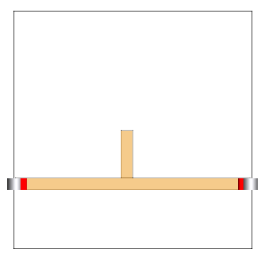
Figure 2. Zoomed in 3D view of one of the microstrip ports. 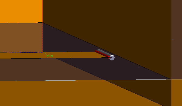
Tip: The microstrip port connects to a single edge and is only used with infinite substrates. The positive terminal is indicated by the red cylinder in the 3D view. - Set a local mesh size on the microstrip lines (faces) of strip_width/2.