Tutorial Level: Beginner Set up a high pressure die casting simulation and see how to troubleshoot it.
In this exercise, you will learn how to run an analysis and prevent typical casting
defects for the high pressure die casting process. The process must balance the need to
fill the mold quickly enough to prevent premature solidification with the need to fill
the mold slowly enough to prevent air mixing with the liquid, causing porosity in the
finished part.
Import Geometry
Before you begin, copy the file(s) used
in this tutorial to your working directory.
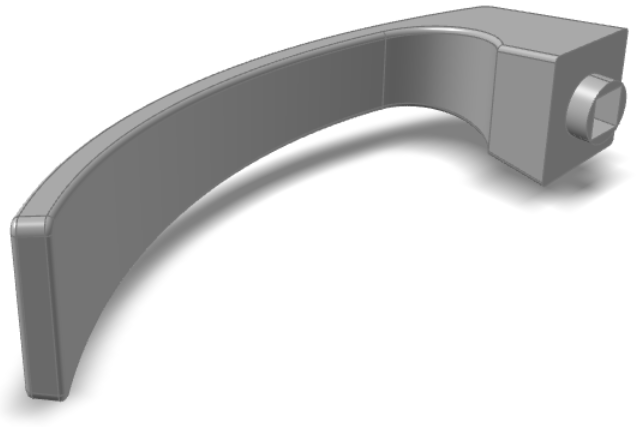
Browse to your working directory, select handle.x_b, and
click Open.
The model opens in the modeling window.
Designate a Cast Part
Click the Casting tab.
On the Cast Part icon, click Designate
Casting Part.
Click on the cast part.
Use the microdialog options to define the material, alloy, and
temperature.
Create an Ingate
Click the Casting tab.
On the Gate icon, click Add/Edit
Gate.
Click on the part to create a virtual gate.
Use the microdialog options to define the gate's position, shape, and
dimensions.
Create a Mold
Click the Casting tab.
Click the Components icon.
Click the Mold icon.
Define the mold material and temperature as shown.
Configure Basic Setup
Click the Casting tab.
Click the Basic Setup icon.
Select Initial Velocity and enter 35 m/s.
Run Analysis
On the ribbon, click the Casting tab.
On the Analysis icon, click Run
Analysis.
Select Run filling analysis and Run
solidification analysis.
Enter an average thickness of 1.53019 mm.
Click Run.
Note: Once the simulation calculation is finished, a green flag will appear on the analyze icon.
Note: The user can also select the results by clicking View
Now under Run History.
Run the Temperature Animation
Click Temperature under Result Types.
Click Play
to start the animation.
View the Porosity Result
Click Demolding under Stage, then
click Porosity under Result
Types.
Note:
To avoid defects like trapped air, we can optimize the size, shape, and
placement of the inlet. Experiment with the gate's configuration and
placement and re-run the analysis to see the difference in the results.
Once you know the optimal configuration of the inlet, you can design a
filling system for high-pressure
casting.
Open the New Model
Use the model provided to run a high-pressure casting analysis.
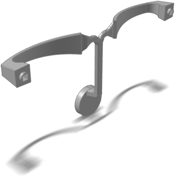
Browse to your working directory, select handlefull.x_b,
and click Open.
The model opens in the modeling window.
Cast Material and Temperature
Click the Casting tab.
On the Cast Part icon, click Designate
Casting Part.
Click on the cast parts.
Use the microdialog options to define the material, alloy, and
temperature.
Designate Filling System
Click the Casting tab.
On the Cast Part icon, click Designate
Filling System.
Click the runner parts.
Right-click and mouse through the check mark to exit, or double-right-click.
Set Gravity Direction
Click the Casting tab.
On the Cast Part icon, click Set Gravity
Direction.
Use the microdialog options to rotate, align, or flip the model with respect to
the direction of gravity (the z-axis).
Right-click and mouse through the check mark to exit, or double-right-click.
Generate a Mold
Click the Casting tab.
Click the Components icon.
Click the Mold icon.
Use the microdialog options to define the material and temperature.
Generate a Shot Sleeve
Click the Casting tab.
Click the Components icon.
Click the Shot Sleeve icon.
Click the ingate surface on the designated runner system. In the microdialog,
set the shot sleeve's diameter to 50 mm and its length to
200 mm. Set the piston's velocity to be
500 mm/s at 0 seconds and
153.32 seconds, and 2500 mm/s
at 161.83 seconds and 200
seconds.
Configure High Pressure Parameters
Click the Casting tab.
Click to select the
High Pressure icon.
Using Shot Sleeve is selected by default. The
Piston velocity control table is already populated
with the data you entered in the previous step. Use the default settings for
Mass, Piston initial
temperature, and Chamber initial
temperature, and the other fields. It is not necessary to select
Show PQ2 diagram or Compute Clamping
Forces.
Note: The first velocity in the Piston Velocity
Control table must move the liquid material slowly enough
that the liquid does not mix with the air inside the shot sleeve. Once the
air is pushed out of the shot sleeve, the piston velocity can
increase.
Run Analysis
Click the Casting tab.
On the Analysis icon, click Run
Analysis.
Select Run a filling analysis and Run a
solidification analysis.
Enter an average thickness of 3.06039 mm.
Click Run.
Note: Once the simulation calculation is finished, a green flag will appear on the analyze icon.
Note: The user can also select the results by clicking View
Now under Run History.
Run the Temperature Animation
Click Temperature under Result Types.
Click Play
to start the animation.
Run the Flow Front Animation
Click Flow Front under Result
Types.
Click Play to start the animation.
Note: The Flow Front animation
shows where air may mix with the liquid material, which can cause porosity
in the finished product.
View Last Air Result
Click Last Air under Result
Types.
Note: The Last Air option shows where air will become
trapped during the filling process. Use this result to help determine where
to place overflow compnents to ensure that no air is left in the part.
View the Porosity Result
Click Demolding under Stage, then
click Porosity under Result
Types.
Note: This result shows where the material is contracting
during solidification, which can cause structural weakness.


 to select the
High Pressure icon.
to select the
High Pressure icon.


