
Tutorial: Adding a Core Component
Tutorial Level: Intermediate See the difference in porosity of a solid model and the same model with a core.
In this exercise, you will learn how to analyze the effect a sand core has on casting.
Import Geometry
- From the menu bar, select .
-
Browse to your working directory, select core.x_b, and
click Open.
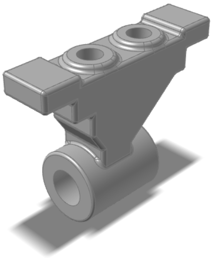
The model opens in the modeling window.
Designate a Casting Part
Select casting geometries with the Cast Part tool.
Important: A cast part must be defined before performing any other
operation.
-
On the Cast Part icon, click Designate
Casting Part.

-
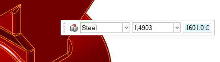
Left-click to select which candidate is a cast part.
Parts are automatically detected and highlighted based on your cursor position.The selected part is highlighted red.

-
In the microdialog, select Steel
as the material and select 1,4903 as the alloy for the
part.
- Right-click and mouse through the check mark to exit, or double-right-click.
Set Gravity Direction
-
On the Cast Part tool, click Set Gravity
Direction.

-
Click the Gravity icon in the microdialog to align gravity to the normal of a selected
surface.

-
Click one of the bottom surfaces of the part.
 Gravity will automatically be realigned perpendicular to the selected surface.
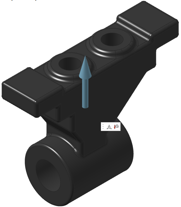
- Right-click and mouse through the check mark to exit, or double-right-click.
Add a Gate
-
On the Gate icon, click Add/Edit
Gate.

-
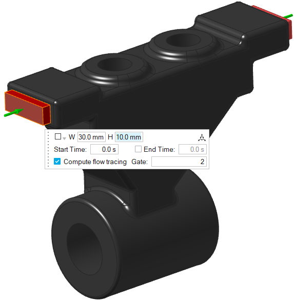
Create two gates: select a surface of the model to place a gate there, and
enter the dimensions in the microdialog as shown below.
Add a Core
-
Click the Components tool.

Click the Core tool in the secondary tool group.
-
Cavities that can become cores are shown in gray. Click to select which
candidate is a core and automatically create the core volume.
The selected part is highlighted red.

-
In the microdialog, select
Silica-Sand as the material.

- Right-click and mouse through the check mark to exit, or double-right-click.

Run Analysis
-
On the Analysis icon, click Run
Analysis.

-
In the Run Analysis dialog, select the
Stages tab and enter the Element
size manually or define the Average
Thickness. You can also select number of cycles in the process
by selecting Use cycling.

-
Select the Advanced tab to manually select mesh factors
for components like gate, mold, runner, riser, etc.

-
Select the Stages tab and click
Run.
Note: The mold will automatically generate when you click Run.Note: Once the simulation calculation is finished, a green flag will appear on the analyze icon.

Analyze Results
-
Click the green flag on the Analyze tool.
You can also select the run and click View Now in the Run Status window.

-
Click Solid Fraction under Result
Types.

-
Set the Solid Fraction percentage to
0.70.

Note: The solid fraction value is set to 0.7 by default. In most cases, this corresponds to the value at which the liquid stops flowing. -
Click Play
to start the animation.

In the animation, solidified material (above 0.7) is transparent, while liquid material (below 0.7) is shown colored. Shrinkage porosity is more likely to occur in isolated areas.
-
Click Demolding under Stage and
click Porosity under Result
Types.

-
Set the percentage to 100%.

There are no regions of 100% porosity in the finished part.