Tutorial: Adding Overflows and Cooling Lines
Observe how a cooler helps maintain a homogeneous temperature range throughout a mold, particularly in high pressure die casting.
In this exercise, you will learn how to analyze the effect cooling channels have on casting.
Model file is available in the tutorial_models folder in the installation directory in Program Files\Altair\2024\InspireCast2024\tutorial_models\cooler.x_b.
Import Geometry
- Launch Inspire Cast.
-
Click Open Model on the Files icon and browse to the
tutorial model file in the installation directory, or drag-and-drop the file
into the modeling window.

Designate a Casting Part
Select casting geometries with the Cast Part tool.
Important: A cast part must be defined before performing any other
operation.
-
On the Cast Part icon, click Designate
Casting Part.

-
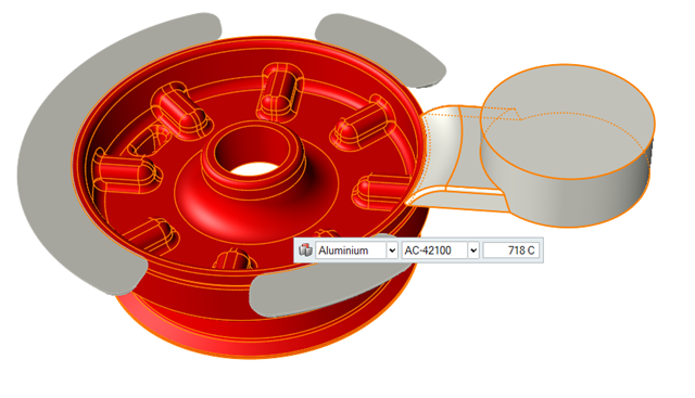
Left-click to select which candidate is a cast part.
Parts are automatically detected and highlighted based on your cursor position.The selected part is highlighted red.
-
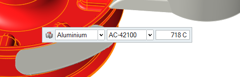
In the microdialog, select
Aluminum as the material and
AC-42100 as the alloy for the part.
- Right-click and mouse through the check mark to exit, or double-right-click.
Select a Filling System
-
On the Cast Part tool, click Designate
Filling System.

-
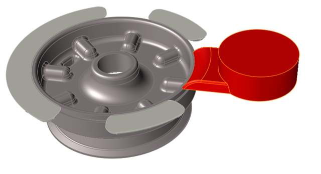
Left-click to select a runner.
Parts are automatically detected and highlighted based on your cursor position.The selected part is highlighted red.
- Right-click and mouse through the check mark to exit, or double-right-click.
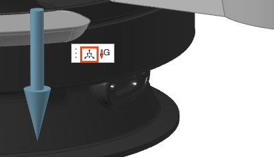
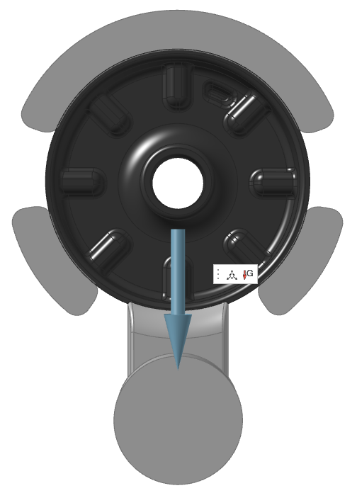
Set Gravity Direction
-
On the Cast Part tool, click Set Gravity
Direction.

-
Click Realign Gravity in the microdialog to rotate the direction of gravity with respect
to the part.
-
Click the X axis arrow and rotate it to 90 deg.
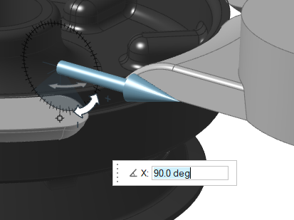
- Right-click and mouse through the check mark to exit, or double-right-click.
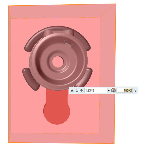
Designate Overflows
-
Click the Components tool.

Click the Designate Components as Overflow tool in the secondary tool group.
-
Select the three overflows.
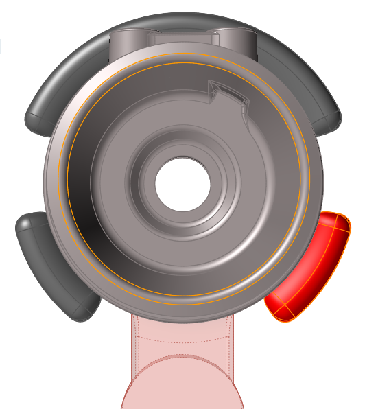
- Right-click and mouse through the check mark to exit, or double-right-click.
Add a Mold
-
Click the Components tool.
Click the Add/Edit Mold tool in the secondary tool group.
-
Select Carbon-Steel and enter 150 C.
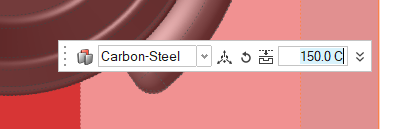
- Right-click and mouse through the check mark to exit, or double-right-click.
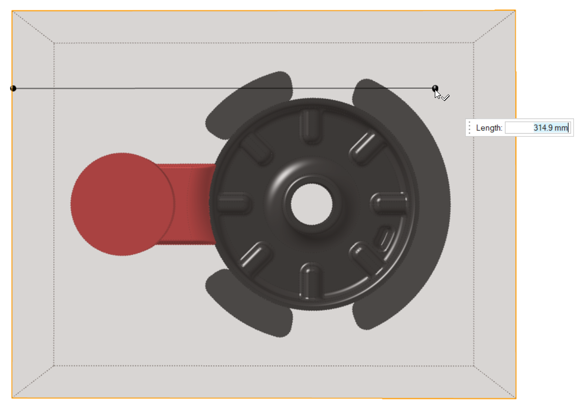
Create Cooling Lines
-
Click the Components tool.
Click the Add/Edit Cooling System tool in the secondary tool group.
-
Click the top face of the mold to start drawing the cooling lines.
The first click will define the initial point of the cooling system. The second click will define the endpoint of the first line of the cooling channels.Note: Press the shift key to force the line direction in right angles.
-
Click to create the cooling lines as shown.
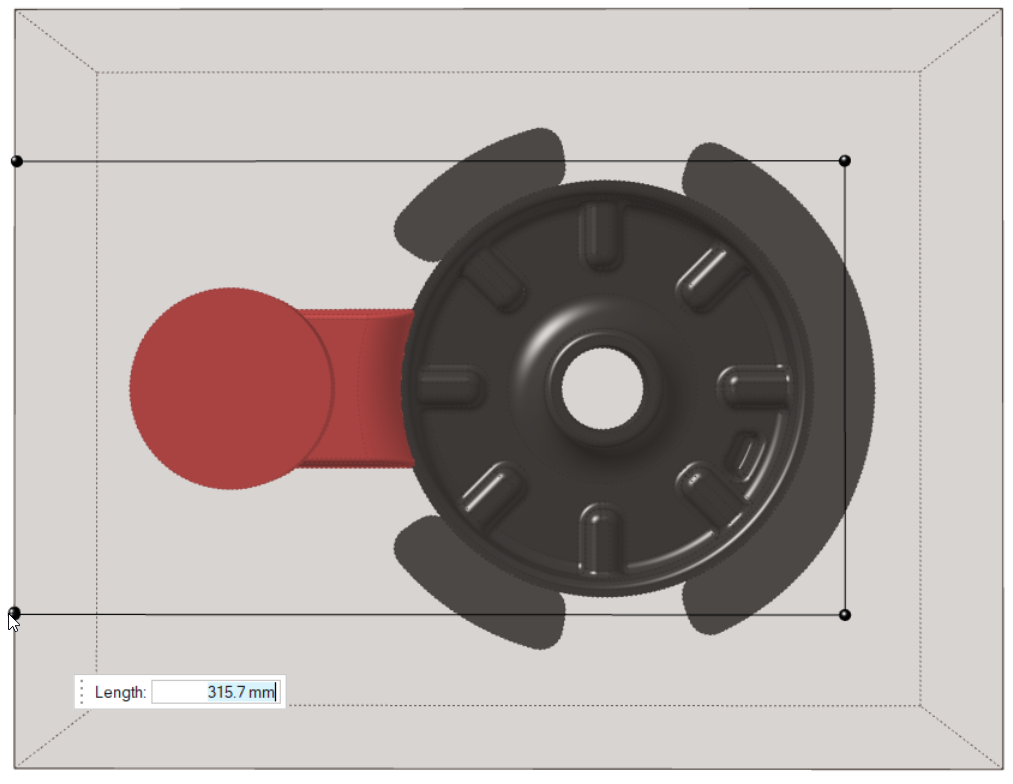
-
Right-click to confirm.
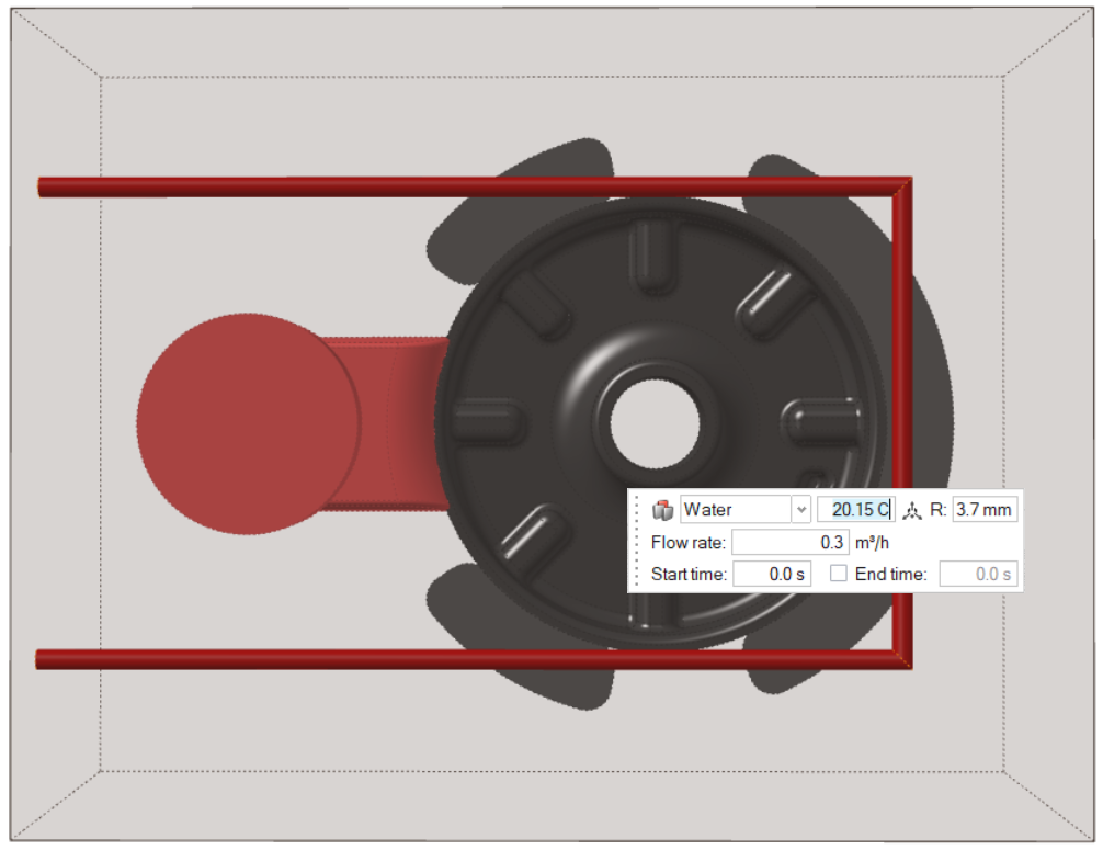
- Use the microdialog to edit the cooling lines.
-
Click Move Component
 and click the Y
arrow to move the lines to the center of the part.
and click the Y
arrow to move the lines to the center of the part.
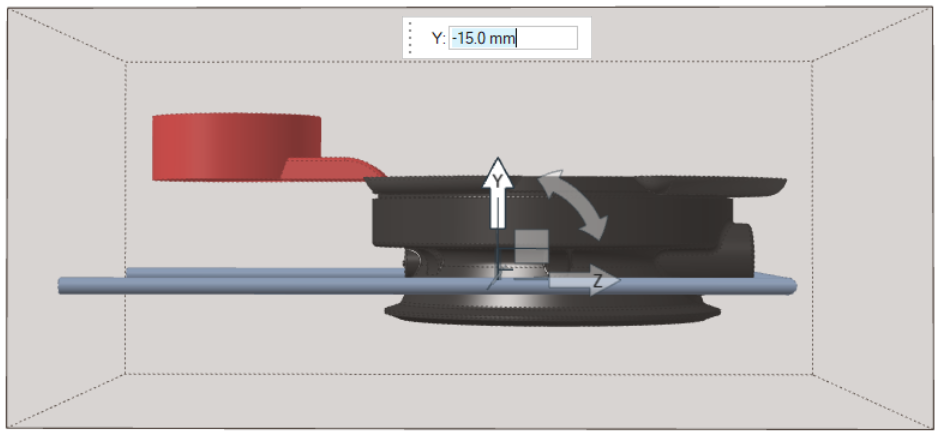
- Right-click to confirm.
-
Change the Radius to 5 mm.
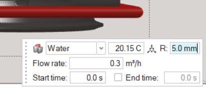
- Right-click outside of the mold area, and then mouse through the check mark to exit.
Run Analysis
-
On the Analysis icon, click Run
Analysis.

-
In the Run Analysis dialog, in the
Stages tab, deselect Run a filling
analysis.
Note: For this demonstration, we do not need a filling analysis. Also, if we did not add a gate, a filling analysis will not run.
-
Select the Advanced tab to manually select mesh factors
for components like gate, mold, runner, riser, etc.

-
Select the Stages tab and click
Run.
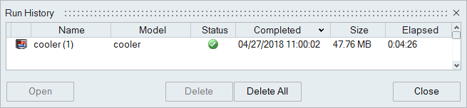
Note: Once the simulation calculation is finished, a green flag will appear on the analyze icon.

Analyze Results
-
Click the green flag on the Analyze tool.
Note: You can also view the results by selecting the run and clicking View Now in the Run Status window.
-
Click Solid Fraction under Result
Types.

-
Set the Solid Fraction percentage to
0.70.

Note: The solid fraction value is set to 0.7 by default. In most cases, this corresponds to the value at which the liquid stops flowing. -
Click Play
to start the animation.

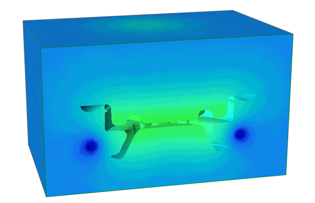
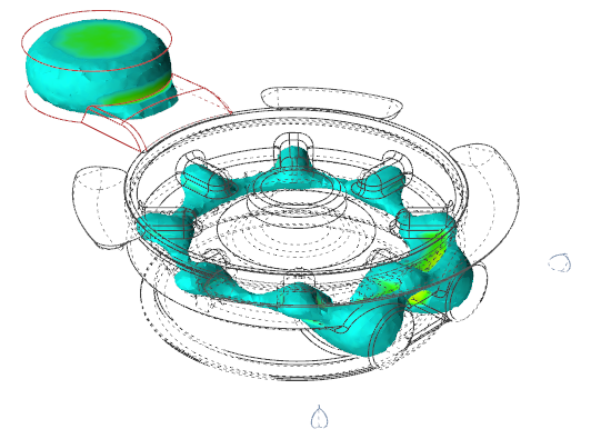
In the animation, solidified material (above 0.7) is transparent, while liquid material (below 0.7) is shown colored. Shrinkage porosity is more likely to occur in isolated areas.We can see how the central region of the part is the final area to solidify so cooling lines will help to refrigerate this region.
-
Click Mold Temperature under Result
Types.

-
Click Play
to start the animation.
Mold temperature shows how the cooling lines are helping to cool down the temperature in the regions where the porosity is.