Input
From the menu bar, click .
Note: You have to import the design file before selecting the
Input option. Refer to PollEx
PCB manual for design file import.
- Analysis
- Analysis queue
- Target Object
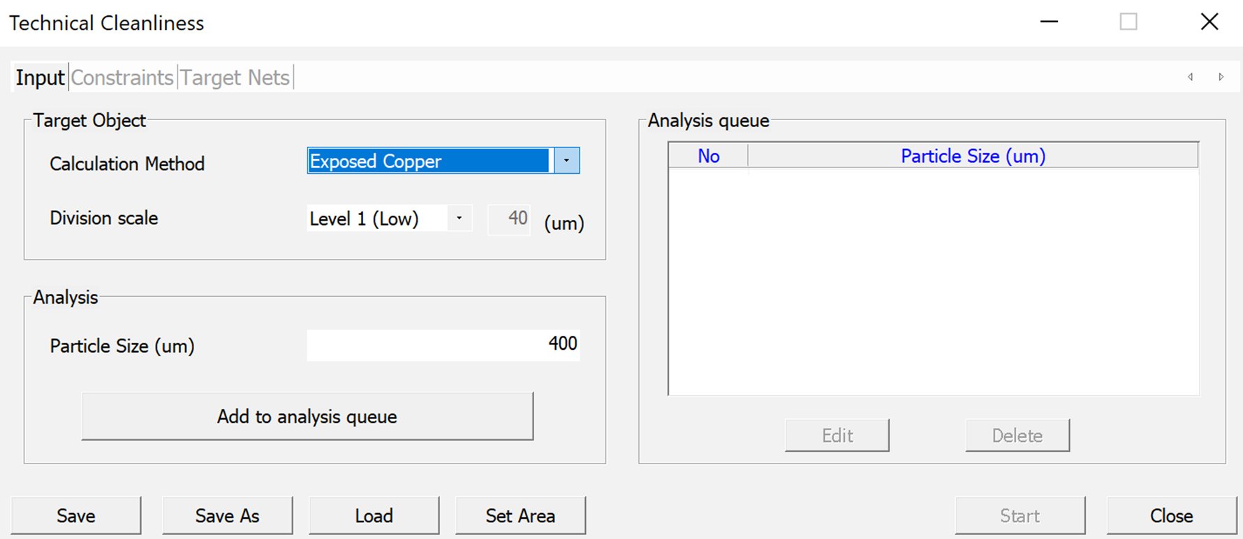
Analysis
PollEx TC perform analysis using parameter from the particle definition and the target object. Once parameter is created and provided as an input, it can be added to the queue list for analysis.
The Analysis panel provides:
- Particle Size: Enter the particle size to be analyzed. The larger the particle size value, the more time required to analyze the hazard area.
- Add to Analysis Queue: Add the parameter to the table listed on the Analysis queue panel.
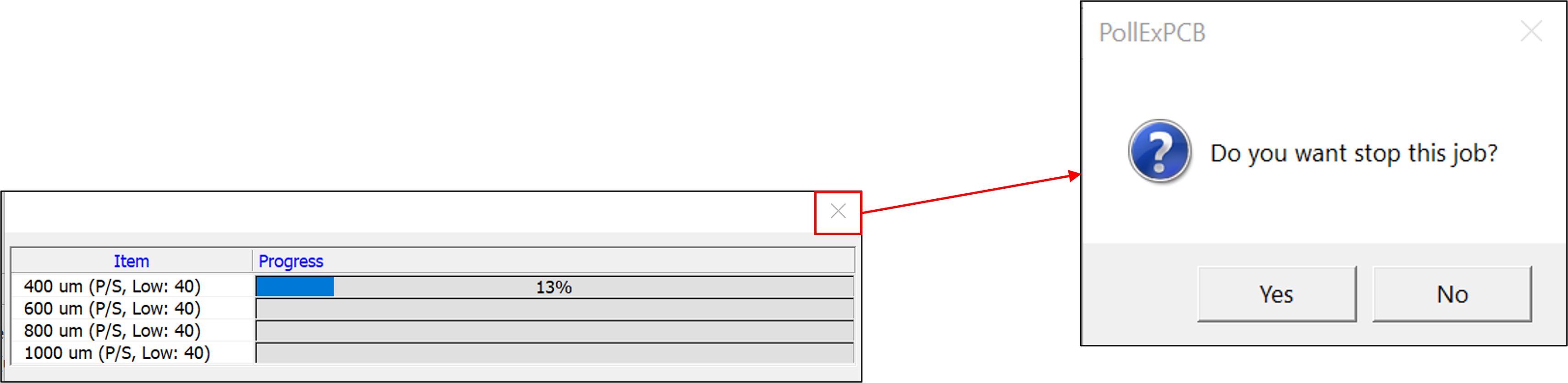
When an analysis is performed a Progress bar tracks the status of the each input parameter.
If any edit are to be made after the analysis has begun, close the progress bar as shown below:
Analysis Queue
Analysis queue lists the parameters for the particle size and selected target object scale to analyze. This menu helps edit or delete the data setting list.
The analysis queue has the following options:
- Edit: Edits a selected parameter.
Figure 3. 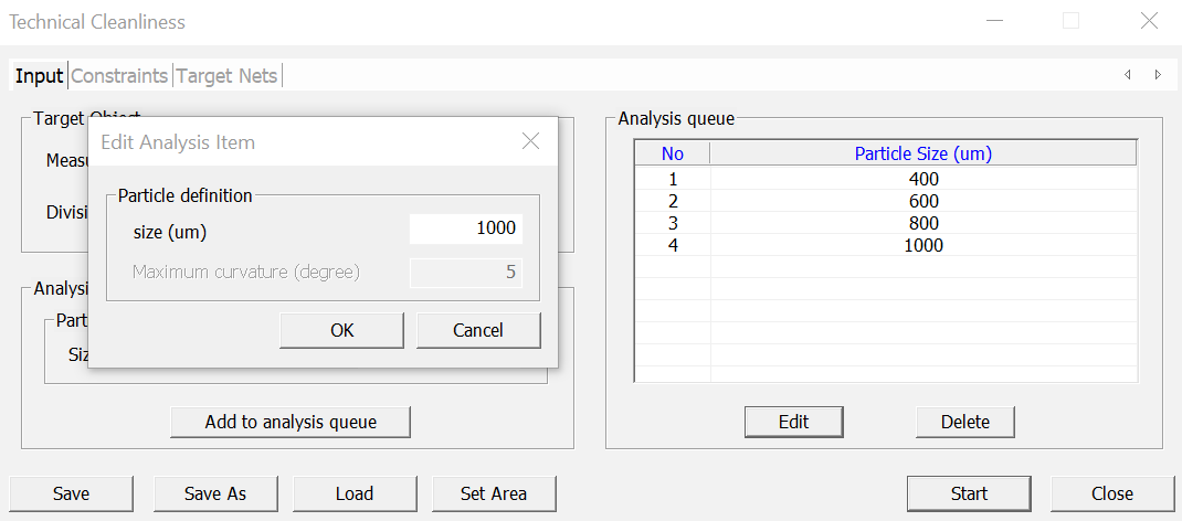
- Delete: Deletes a selected parameter from the queue.
Figure 4.
Target Object
Target Object defines the selected area and level.
It has two options namely:
- Calculation Method: Selects the area which will be measured. There are two bases available, Exposed Copper, and SolderMask.
- Division Scale: Sets the partition size of the object (Copper) required for the hazard area analysis. The smaller the size of the partition the more precise the inspection.