Hole Distance
Check the clearance between the hole and other objects such as other holes, routing patterns, test points, or pads.
The Hole Distance dialog contains the following sections:
- Hole Definition: Define the target holes to be checked.
Target could be a via, DIP type pin hole, or board figure holes.
- Via Hole: If you want to include a via hole in
the target objects, use this option.
- Laser Via: Define a laser via.
- Maximum Hole Size: Define the via with maximum hole size that same and smaller holes will be recognized as a lyer via.
- Padstack List: Define the via using padstack name.
- Padstack String: Define the via
using string filter.
- Import(.txt): Apply
Filter Type based on the characters entered in the
.txt file.
- Apply as a prefix when (|F|) ABC is entered in the .txt file.
- Apply as a mid-string when ABC is entered in the .txt file.
- Apply as a suffix when ABC(|P|) is entered in the .txt file.
- Export(.txt): Export the characters registered in the String Item in .txt file format.
- Import(.txt): Apply
Filter Type based on the characters entered in the
.txt file.
- Laser Via: Define a laser via.
- DIP Pad Hole: Use this option, to make the DIP
type component pin hole into target objects.
- Padstack String: Define the via using
string filter.
- Import(.txt): Apply Filter Type
based on the characters entered in the .txt file.
- Apply as a prefix when (|F|) ABC is entered in the .txt file.
- Apply as a mid-string when ABC is entered in the .txt file.
- Apply as a suffix when ABC(|P|) is entered in the .txt file.
- Export(.txt): Export the characters registered in the String Item in .txt file format.
- Import(.txt): Apply Filter Type
based on the characters entered in the .txt file.
- Padstack String: Define the via using
string filter.
- Board Figure Hole: To make a board figure hole
a checking target object.
- Pad Size: Set the hole size ranges.
- Padstack String: Define the via using
string filter.
- Import(.txt): Apply Filter Type
based on the characters entered in the .txt file.
- Apply as a prefix when (|F|) ABC is entered in the .txt file.
- Apply as a mid-string when ABC is entered in the .txt file.
- Apply as a suffix when ABC(|P|) is entered in the .txt file.
- Export(.txt): Export the characters registered in the String Item in .txt file format.
- Import(.txt): Apply Filter Type
based on the characters entered in the .txt file.
- Exceptional Objects: Among target objects, if
you want to exclude objects from target, specify excluding objects
conditions.
- Hole Size Range: If you specify the hole size ranges, they will be excluded in checking. Use the floating value input tool to define the hole size range.
- Component Group Selection: If holes are registered in a component group and you want to exclude them in checking, specify them by selecting the component group(s).
- Net Selection from Netlist: If you want to exclude net-connected vias holes or net-connected pins holes in checking, select the net from the net list.
- Net Selection using Naming Filter: If
you want to exclude net-connected vias holes or
net-connected pins holes in checking, specify the net using
the net name filtering tool.
- In the dialog, select filter type and given
character string into edit box. For example, if you
select filter type Prefix, enter
AD in the edit box and
click ADD String, character
string
(|F|)ADwill be automatically inserted in the string item list. It means that all nets with names starting with AD will be selected. Nets with the names, ADD1, ADD2, ADDRESS1 will be excluded in checking.
- In the dialog, select filter type and given
character string into edit box. For example, if you
select filter type Prefix, enter
AD in the edit box and
click ADD String, character
string
- Board Figure hole with the geometry
value: (Only ODB++) If you want to exclude a
specific Board Figure hole, use the string filter to specify
its geometry.Note: Please refer to the above explanation for a description of string filtering.
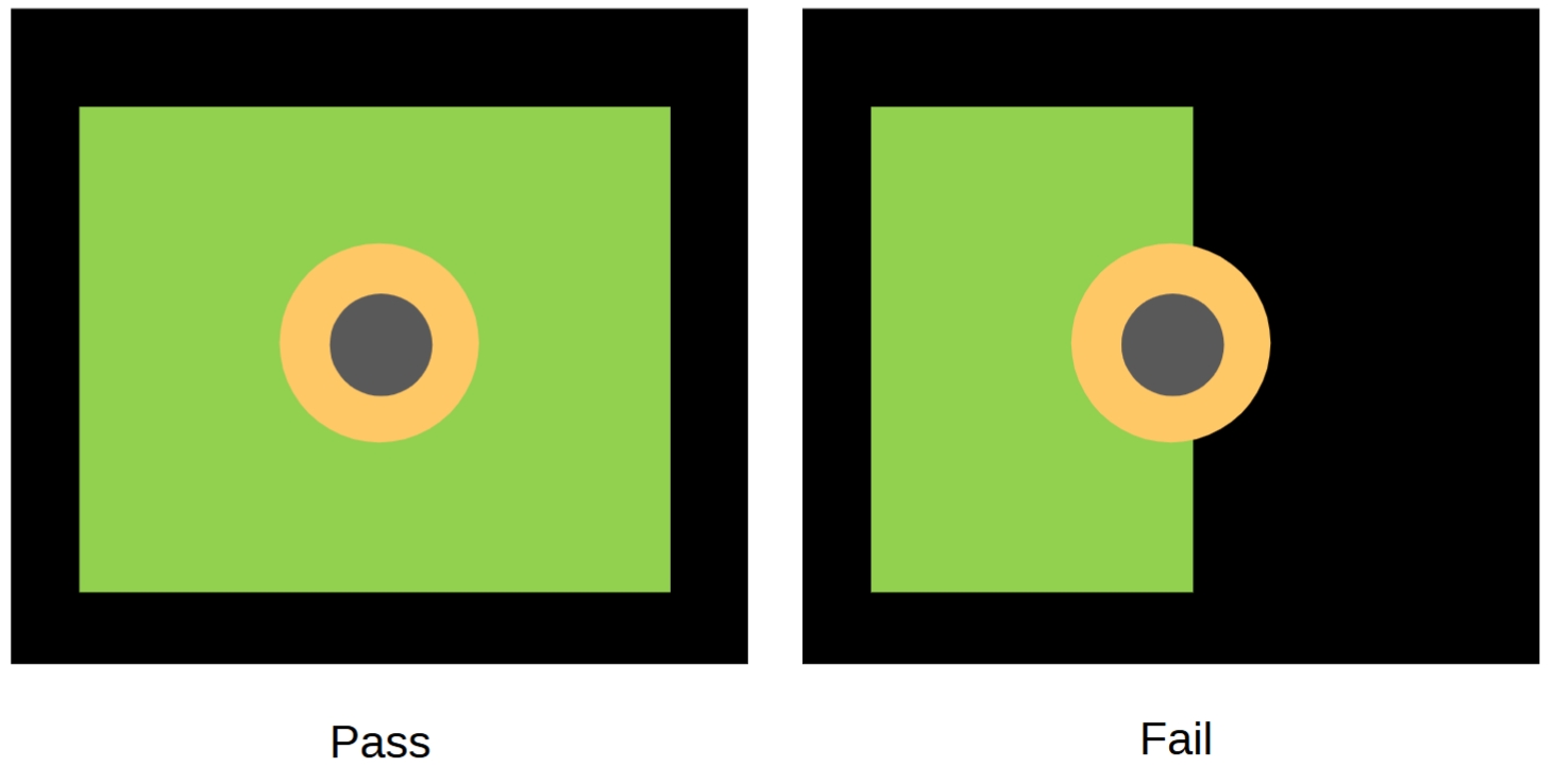
- Hole on the Outside of BoardOutline: Holes placed outside of the BoardOutline area are excluded from checking.
- Via Hole: If you want to include a via hole in
the target objects, use this option.
- Checking: Check various clearances between the
specified hole and other objects.
- Clearance to Other Holes: To check the
clearance to the other holes, set the clearance value.
- Check Clearance with Individual Holes in
Group: For grouped holes, if this option is
enabled, PollEx DFM checks all
clearances between the target hole and all individual holes
in the group.
Figure 1. 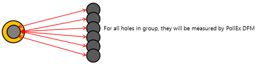
- Allows overlapped holes with matching locations: Allow if the coordinates of two different holes match.
- Check Clearance with Individual Holes in
Group: For grouped holes, if this option is
enabled, PollEx DFM checks all
clearances between the target hole and all individual holes
in the group.
- Clearance to Via Pad: To check the clearance to
the via pad, set the clearance value.
- Increase Clearance (longer axis): When you enter a value for Increase Clearance, it becomes an added value to the existing Clearance. (When 'Increase Clearance' is checked, the existing 'Clearance' is applied to the short side)
- Clearance to Laser Via Pad: To check the clearance to the laser via pad, set the clearance value.
- Clearance to Test Points: To check the
clearance to the test points, set the clearance value.
- Increase Clearance (longer axis): When you enter a value for Increase Clearance, it becomes an added value to the existing Clearance. (When 'Increase Clearance' is checked, the existing 'Clearance' is applied to the short side)
- NPTH Clearance to Solder Mask: To check the clearance to the solder mask and Non-Plated Through Hole (NPTH), set the clearance value.
- PTH Clearance to Solder Mask: To check the clearance to the solder mask and Plated Through Hole (PTH), set the clearance value.
- NPTH Clearance to Metal Mask: To check the clearance to the metal mask and Non-Plated Through Hole (NPTH), set the clearance value.
- PTH Clearance to Metal Mask: To check the clearance to the metal mask and Plated Through Hole (NPTH), set the clearance value.
- Solder Mask Annular Ring: Check the clearance
to the Hole edge and PSR (Solder Resist), set the clearance
value.
- NPTH: Check the NPTH pad.
- Slot NPTH: Check the Slot NPTH pad.
- Clearance to Board Outline: To check the
clearance to the board outlines edge, set the clearance value.
- Except for Overlapped Hole (Distance
0.0): If this option is on, PollEx DFM skips checking for holes
overlapped with board outline.
Figure 2. 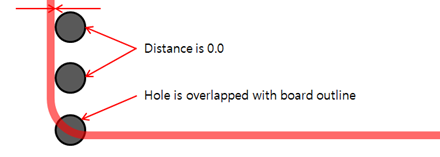
- Except for Overlapped Hole (Distance
0.0): If this option is on, PollEx DFM skips checking for holes
overlapped with board outline.
- Clearance to Routing Patterns: Check clearance
between the target hole and routing patterns.
- Clearance to All Routing Patterns: Set
the clearance value between the target hole and all routing
patterns.
- NPTH Clearance: To check the
clearance to the routing patterns and NPTH, set the
clearance value.
- Increase Clearance (longer axis): When you enter a value for Increase Clearance, it becomes an added value to the existing Clearance. When Increase Clearance is checked, the existing Clearance is applied to the short side.
- PTH Clearance: To check the
clearance to the routing patterns and PTH, set the
clearance value.
- Increase Clearance (longer axis): When you enter a value for Increase Clearance, it becomes an added value to the existing Clearance. When Increase Clearance is checked, the existing Clearance is applied to the short side.
- NPTH Clearance: To check the
clearance to the routing patterns and NPTH, set the
clearance value.
- Clearance to Special Net Groups: If you
want to check the clearance between the target hole and
certain net routing patterns, select net from the list and
assign a clearance value.
- Item: Specify the item name.
- Select Net: Select net from the net list used in design.
- Hole Type: Select the type of target hole (All, NPTH, PTH).
- Top: Set the clearance between the routing pattern of the specified net and target hole in the top layer.
- Bottom: Set the clearance between the routing pattern of the specified net and target hole in the Bottom layer.
- Inner: Set the clearance between the routing pattern of the specified net and target hole in the inner layer.
- Increase Clearance (longer axis): When you enter a value for Increase Clearance, it becomes an added value to the existing Clearance. When Increase Clearance is checked, the existing Clearance is applied to the short side.
- Clearance to Remainder.
- NPTH Clearance: Set the
clearance value between undefined nets routing
patterns and NPTH.
- Increase Clearance (longer axis): When you enter a value for Increase Clearance, it becomes an added value to the existing Clearance. When Increase Clearance is checked, the existing Clearance is applied to the short side.
- PTH Clearance: Set the
clearance value between undefined nets routing
patterns and PTH.
- Increase Clearance (longer axis): When you enter a value for Increase Clearance, it becomes an added value to the existing Clearance. When Increase Clearance is checked, the existing 'Clearance' is applied to the short side.
- NPTH Clearance: Set the
clearance value between undefined nets routing
patterns and NPTH.
- Clearance to All Routing Patterns: Set
the clearance value between the target hole and all routing
patterns.
- Clearance to Copper-Pours: Check clearance
between the target hole and copper-pours.Note: Except for holes in the copper-pour area: Exclude from the inspection if the hole is completely within the copper.
- Clearance to All Copper-Pours: Set the
clearance value between the target hole and all
copper-pours.
- NPTH Clearance: To check the
clearance to copper-pours and NPTH, set the
clearance value.
- Increase Clearance (longer axis): When you enter a value for Increase Clearance, it becomes an added value to the existing Clearance. When Increase Clearance is checked, the existing Clearance is applied to the short side.
- PTH Clearance: To check the
clearance to copper-pours and PTH, set the clearance
value.
- Increase Clearance (longer axis): When you enter a value for Increase Clearance, it becomes an added value to the existing Clearance. When Increase Clearance is checked, the existing Clearance is applied to the short side.
- NPTH Clearance: To check the
clearance to copper-pours and NPTH, set the
clearance value.
- Clearance to Special Net Groups: If you
want to check the clearance between the target hole and
certain nets copper-pour, select net from the list and
assign a clearance value.
- Item: Specify the item name.
- Select Net: Select net from the net list used in design.
- Hole Type: Select the type of target hole (All, NPTH, PTH).
- Top: Set the clearance between the copper-pour of a specified net and the target hole in the top layer.
- Bottom: Set the clearance between the copper-pour of a specified net and the target hole in the bottom layer.
- Inner: Set the clearance between the copper-pour of a specified net and the target hole in the inner layer.
- Increase Clearance (longer axis): When you enter a value for Increase Clearance, it becomes an added value to the existing Clearance. When Increase Clearance is checked, the existing Clearance is applied to the short side.
- Clearance to Remainder: Set the
clearance value between undefined nets copper-pours
and the target hole.
- NPTH Clearance: Set the
clearance value between undefined nets
copper-pours and NPTH.
- Increase Clearance (longer axis): When you enter a value for Increase Clearance, it becomes an added value to the existing Clearance. When Increase Clearance is checked, the existing Clearance is applied to the short side.
- PTH Clearance: Set the
clearance value between undefined nets
copper-pours and PTH.
- Increase Clearance (longer axis): When you enter a value for Increase Clearance, it becomes an added value to the existing Clearance. When Increase Clearance is checked, the existing Clearance is applied to the short side.
- NPTH Clearance: Set the
clearance value between undefined nets
copper-pours and NPTH.
- Clearance to All Copper-Pours: Set the
clearance value between the target hole and all
copper-pours.
- Clearance to Pads: Check the clearance between
the target hole and the component pads.
- Pin Type: Depending on the pad type,
you can define different clearance values.
- NPTH Clearance: To check the
clearance to pads and NPTH, set the clearance value.
- SMD: Set the clearance value between the target hole and the SMD type pins.
- DIP: Set the clearance value between the target hole and the DIP type pins.
- Increase Clearance (longer
axis): When you enter a value for
Increase Clearance, it becomes an added value to
the existing Clearance. When Increase Clearance is
checked, the existing Clearance is applied to the
short side.
- SMD: Set the clearance value between the target hole and the SMD type pins.
- DIP: Set the clearance value between the target hole and the DIP type pins.
- PTH Clearance: To check the
clearance to pads and PTH, set the clearance value.
- SMD: Set the clearance value between the target hole and the SMD type pins.
- DIP: Set the clearance value between the target hole and the DIP type pins.
- Increase Clearance (longer
axis): When you enter a value for
Increase Clearance, it becomes an added value to
the existing Clearance. When Increase Clearance is
checked, the existing Clearance is applied to the
short side.
- SMD: Set the clearance value between the target hole and the SMD type pins.
- DIP: Set the clearance value between the target hole and the DIP type pins.
- NPTH Clearance: To check the
clearance to pads and NPTH, set the clearance value.
- Component Group: Check clearance
between the target hole and certain component group pads.
- Item: Specify the item name.
- Component Group: Select the target component group from the component group list.
- Hole Type: Select the type of target hole (All, NPTH, PTH).
- Clearance: Set the clearance value between the target hole and pins of specified components in groups.
- Increase Clearance (longer axis): When you enter a value for Increase Clearance, it becomes an added value to the existing Clearance. When Increase Clearance is checked, the existing Clearance is applied to the short side.
- Skip to check same component pin: If the target hole belongs to a specified component, PollEx DFM can skip checking.
- Except for SMD Pins, not having Metal Mask: If the specified component pins are SMD type and do not have a metal mask, PollEx DFM can skip them.
- Except for Thermal Pad: When verifying Clearance to Pads, exclude Thermal Pads.
- Pin Type: Depending on the pad type,
you can define different clearance values.
- Clearance to Component: Check the clearance
between holes and components.
- Item: Specify the item name.
- Component Group: Select the target component group from the component group list.
- Measure Base: Set the target component measurement base.
- Hole Type: Select the type of target hole (All, NPTH, PTH).
- Clearance: Set the clearance value between the target hole and pins of specified components in groups.
- Increase Clearance (longer axis): When you enter a value for Increase Clearance, it becomes an added value to the existing Clearance. When Increase Clearance is checked, the existing Clearance is applied to the short side.
- Overlapping Check with Silkscreen: Check if the
target holes overlapping with silkscreen, belong to the components
or board.
- Component Text String: Target silkscreen is the component text string on the silkscreen layer.
- Component Figure: Target silkscreen is the component figure on the silkscreen layer.
- Board Text String: Target silkscreen is the board text string on the silkscreen layer.
- Board Figure: Target silkscreen is the board geometry on the silkscreen layer.
- Clearance to Other Holes: To check the
clearance to the other holes, set the clearance value.