Inputs
1. Introduction
The total number of user inputs (parameters) is equal to four in addition to magnet temperature. All these are advanced input parameters.
2. Standard inputs
No standard user inputs are needed.
3. Advanced inputs
3.1 Number of computations per cogging torque period
The computation of cogging torque versus the rotor angular position is performed using a Finite Element Modeling (Flux software).
“No. comp. / cogging period” (Number of computations per cogging torque period) influences the accuracy of results and the computation time.
The default value is equal to 45. The minimum allowed value is 13. This default value provides a good compromise between the accuracy of results and computation time.
3.2 Maximum harmonic order
The cogging torque is computed over one cogging torque period.
Harmonics are extracted from the frequency analysis (F.F.T. Fast Fourier Transform) of the cogging torque signal versus rotor angular position.
The order of harmonics displayed on bar graphs and in tables can be selected with this advanced user input parameter “Max. harmonic order” (Maximum harmonic order selected for visualization).
Note: From mathematical point of view, the maximum allowed harmonic order depends on the number of computations per electrical period. In case of too small number of computations per electrical period, the harmonic order considered will be lower than which user has set.
The default value is equal to 20. The minimum allowed value is 1.
3.3 Rotor initial position
The computations are carried out by considering a given initial relative angular position between the rotor and the stator.
This initial relative angular position of the rotor must be set in the field « Rotor initial position ».
This relative angular position corresponds to the angular distance between the direct axis of the rotor north pole and the axis of the stator phase 1 (reference phase). The default value is equal to 0. The range of possible values is [-360, 360].
For more details, please refer to the section dedicated to the generic information.
3.4 Skew model – Number of layers
3.5 Airgap mesh coefficient
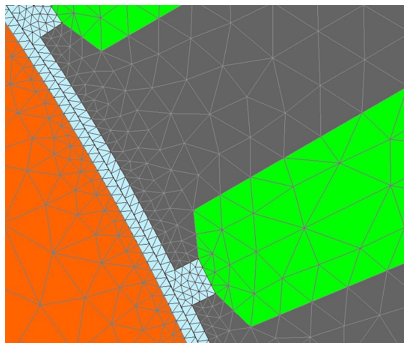
The airgap mesh density is a very sensitive parameter for cogging torque computation. To get better results, sometimes it is necessary to modify the default applied mesh.
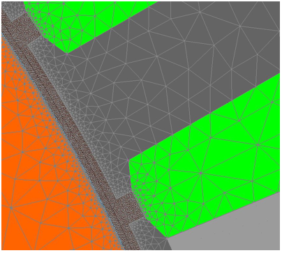
The advanced user input “Airgap mesh coefficient” is a coefficient, which adjusts the size of mesh elements inside the airgap. When the value of “Airgap mesh coefficient” decreases, the mesh elements get smaller, leading to a higher mesh density inside the airgap, increasing the computation accuracy.
The imposed Mesh Point (size of mesh elements touching points of the geometry), inside the Flux software, is described as:
MeshPoint = (airgap) x (airgap mesh coefficient)
Airgap mesh coefficient is set to 0.45 by default.
The variation range of values for this parameter is [0.05; 2]
0.05 giving a very high mesh density and 2 giving a very coarse mesh density.
However, this always leads to a huge number of nodes in the corresponding finite element model. So, it means a need of huge numerical memory and increases the computation time considerably.
 |
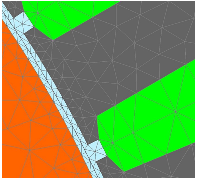 |
| Airgap mesh density = 0.45 = default value | Airgap mesh density = 1.0 |
 |
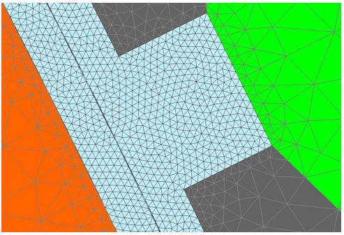 |
| Airgap mesh density = 0.1 | Airgap mesh density = 0.1 (zoomed view) |