Datasheet - Motor - I U
1. Positioning and objective
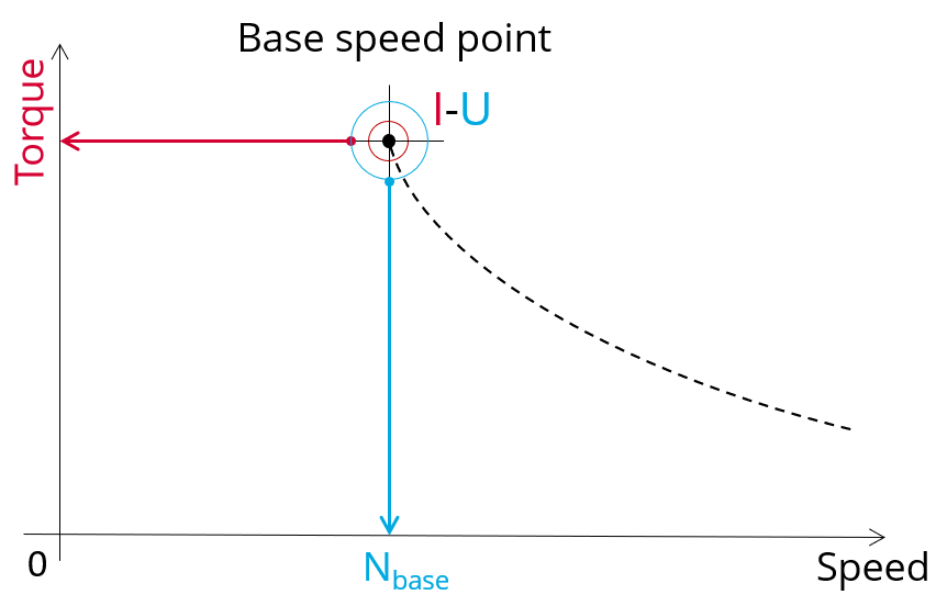
The aim of the test “ Characterization - Datasheet – Motor – I, U ” is to characterize the behavior of the machine when operating at the working point that is located at the base speed point.
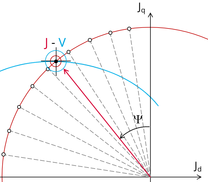
The working point or base speed point of the torque-speed curve is defined by considering the maximum allowed line-line voltage and the maximum allowed line current.
If it is not the case, we called as “Corner speed point”.
 |
 |
| Characterization of the base speed point on the torque speed curve | |
This test gives an overview of the electromagnetic analysis of the motor considering the machine topology, the maximum allowed supplied line-line voltage and line current.
For this working point, general data of the machine, like machine constants, power balance and magnet behavior are computed and displayed. The magnetic flux density is also computed in every part of the machine to evaluate the design.
The test results also include all the necessary constants to build the equivalent model of the machine and to simulate the behavior of the machine in its electrical environment. In the results, a set of inductances is computed (unsaturated and at the base speed point).
The ripple torque at the base speed point is computed.
An overview of the machine performance at no-load is also given in this test.
The following table helps to classify the test “Characterization – Datasheet – Motor – I, U”.
| Family | Characterization |
| Package | Datasheet |
| Convention | Motor |
| Test | I, U |
| Positioning of the test “Characterization – Datasheet - Motor - I,U” | |
2. User inputs
The main user input parameters to perform this test are the maximum allowed supplied Line-Line voltage and Line current.
In addition, temperatures of winding and magnets have to be set.
The main user input parameters to perform this test are the maximum allowed supplied line-line voltage, the line current and the command mode. In addition, temperatures of winding and magnets must be set.
3.Main outputs
Test results are illustrated with data, graphs and tables
3.1 Tables of results
-
Machine performance – Base speed point
- General data
- Machine constants
- Power balance
- Flux in airgap
- Flux density in iron
- Magnet behavior including evaluation of demagnetization rate
-
Power electronics
- Inverter
- Working point
-
Inductances
- Unsaturated inductances
- Base speed point
- D-Q model representation
-
Machine performance – open circuit
- Back emf characteristics
- Flux in airgap
- Flux density in iron
- Magnet behavior including evaluation of demagnetization rate
-
Ripple mechanical torque
- Working point
-
Synthesis for catalog
- Operating conditions
- Performance
- Machine characteristics
- Masse & Inertia
3.2 Curves
- Ripple mechanical torque versus rotor angular position
- Mechanical torque versus current and control angle
- Phase voltage versus time – Open circuit
- Line-line voltage versus time – Open circuit
- Flux linkage versus rotor angular position – Open circuit
- Flux density in airgap versus rotor angular position – Open circuit