Working point - U, f, N
1. Positioning and objective
The aim of the test “Mechanics – NVH – Working point – U-f-N” is to perform NVH analysis of the machine when operating at the targeted working point defined with the following inputs values U, f, N (Line-Line voltage, Power supply frequency, Speed).
This test is available only in the beta mode. It means that all the computation process and results are not entirely qualified yet. However, this gives users, the capability to use and to evaluate this new feature by themselves.
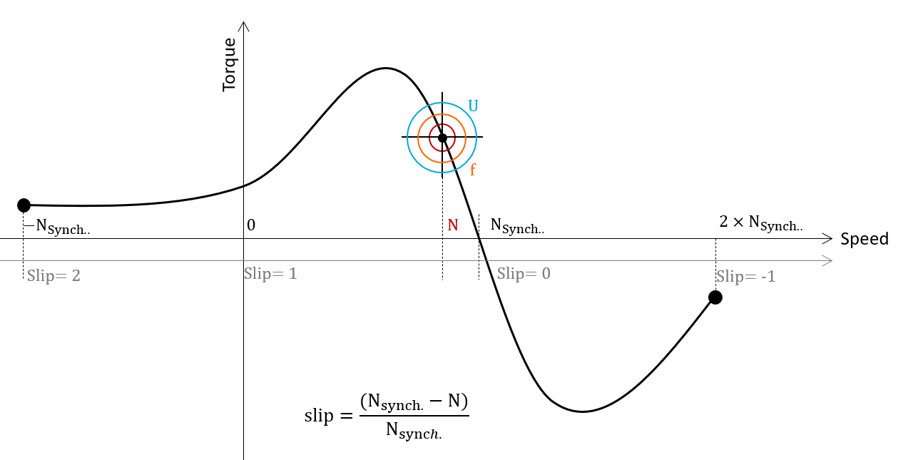 |
| “Working point – Sine wave – Motor – U, f, N” Illustration |
This test give data allowing NVH prediction in early electromagnetic and design stage.
The modal analysis of the stator mechanical structure, the sound power level and the magnetic forces applied on teeth are computed and displayed.
This test helps to answer the following question:
- Could the machine have any risks in connection with NVH? Yes / No.
The following table helps to classify the test “Mechanics – NVH – Working point – U-f-N”.
| Family | Mechanics |
| Package | NVH |
| Convention | # |
| Test | Working point - U - f - N |
| Positioning of the test “Mechanics – NVH – Working point – U-f-N”. | |
2. User inputs
The three main user input parameters are the supplied Line-Line voltage, the power supply frequency, and the speed (or the slip). In addition, temperatures of winding and squirrel cage must be set.
3. Main outputs
Test results are illustrated with data, graph, and tables.
-
Tables of results
- Machine performance - Working point defined with U-f-N
-
Graphs, curves, and maps to illustrate NVH analysis results
- Modal analysis
- Radiation efficiency
- Space-Time normal flux density in the airgap
- Space-Time Maxwell pressure
- Sound power level
- Electromagnetic forces on teeth