Work. Pt - Sine wave - Motor - I PSI N
1. Positioning and objective
The aim of the test “Working point – Sine wave – Motor – I, Ψ, N” is to characterize the behavior of the machine when operating at the targeted input values I, Ψ, N (Magnitude of current, Control angle, Speed).
These three inputs are enough to impose a precise working point.
For instance, a working point can be chosen on the efficiency map, by identifying the current, the control angle and the speed with different curves or maps displayed in the “Performance mapping / Sine wave / Motor / Efficiency map” test. Then, the “Working point – Sine wave – Motor – I, Ψ, N” test allows to compute the performance for this working point.
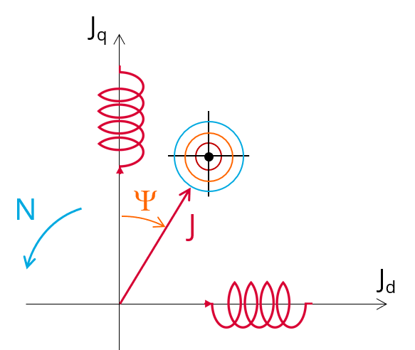 |
| “Working point – Sine wave – Motor – I, Ψ, N” illustration |
The results of this test give an overview of the electromagnetic analysis of the machine considering its topology.
The general data of the machine, like machine constants and power balance are computed and displayed. The motor convention is used to build the model.
The magnetic flux density is also computed in every region of the machine’s magnetic circuit to evaluate the design.
Two computation modes are available:
- “Fast computation mode” is perfectly suited for the pre-design step (Hybrid model based on Magneto-Static Finite Element computations and Park transformation theory)
- “Accurate computation mode” is perfectly suited for the final design step (Pure Finite Element modeling based on transient computations)
It also gives the capability to make comparisons between the results obtained from the measurements and those evaluated with our software .
When both the following conditions are met, this test allows to perform electromagnetic computations with coupled thermal analysis:
- The type of machine is Reluctance Synchronous Machine with Inner rotor
- One of the two following thermal solving modes is selected: One iteration or iterative solving mode
The following table helps to classify the test “Working point – Sine wave – Motor – I, Ψ, N”.
| Family | Working point |
| Package | Sine wave |
| Convention | Motor |
| Test | I, Ψ, N |
| Positioning of the test “Working point – Sine wave – Motor – I, Ψ, N” | |
2. User inputs
The three main user input parameters are the supply line current, control angle and speed. In addition, temperatures of winding must be set.
3. Main outputs
Test results are illustrated with data, graphs, and tables
3.1 Tables of results
-
Machine performance – Working point
- General data
- Machine constants
- Power balance
- Flux in airgap
- Flux density in iron
-
Power electronics
- Inverter
- Working point
-
Inductances
- Working point
- D-Q model representation
-
Ripple mechanical torque
- Working point
-
Thermal data
- Table of temperatures
3.2 Curves – in the “Fast computation modes”
- Ripple mechanical torque versus rotor angular position
- Flux density in airgap versus rotor angular position
- Chart of temperature (radial and axial views)
3.3 Curves – in the “Accurate computation modes”
- Mechanical torque versus rotor angular position
- Mechanical torque harmonic analysis
- Flux density in airgap versus rotor angular position
- Flux density in airgap harmonic analysis
- Phase voltage versus rotor angular position
- Phase voltage harmonic analysis
- Phase current versus rotor angular position
- Phase current harmonic analysis
3.4 Graphics
- Isovalues
3.5 Temperatures
- Chart of temperature (radial and axial views)
-
Thermal data
- Table of temperatures