Co-Simulation with Modelica
チュートリアルレベル:アドバンストLearn how to properly build FMUs out of a Modelica component and how to couple FMUs (also from other tools and models) with Modelica components.
このチュートリアルのファイル
FMU with Modelica.scm:このファイルには、このチュートリアルで説明した概念に従ったシステムが含まれていますが、必ずしもすべてのコンポーネントが同じとは限りません。
Overview
An overview of the concepts and objectives of the tutorial.
Functional Mockup Units (FMUs) are standard blocks that can enclose any dynamic model into a standardized interface, allowing for an easy interaction with the components of the importing framework.
While both building and linking to FMUs, it is important to understand how to properly split the model to allow for an effective coupling between the co-simulation environment and the FMU itself.
When it comes to Modelica components, you must also consider an additional conversion: although FMU blocks requires pure numerical signals at their interface, Modelica components are usually connected through “physical” connection. For example, a connection between a spring and a mass appears as a single link, but it internally connects two numerical sub-signals, namely the position and the force.
For this reason, Modelica “physical” connections should be exploded into their underlying numerical signals before being wrapped into an FMU. The Modelica Standard Library already offers these physical-numerical adapters for the various domains (Electrical, Mechanical, etc).
- Choosing the perimeter separating the FMU from the context.
- Converting Modelica connections into numeric signals.
- Understanding which signals should be set as input or as output.
- Wrapping a part of a model into an FMU or replacing a part of a model with an FMU.
Splitting the Model
Demonstration of how the engine and load subsystems are split.
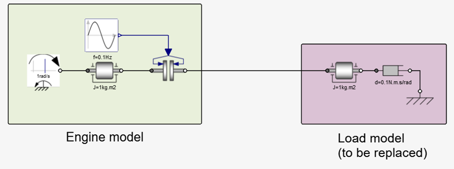
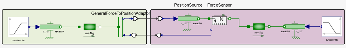
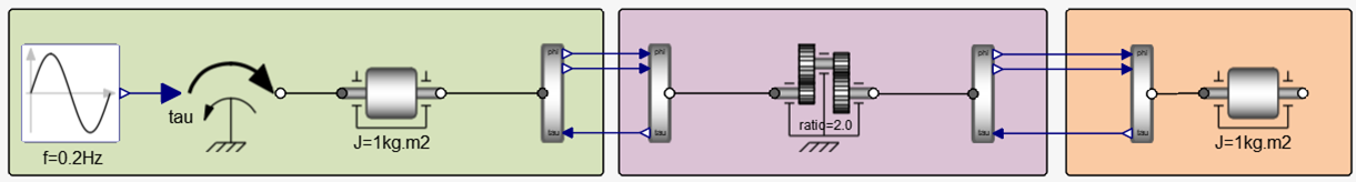
The example consists of two main parts: an engine subsystem and a load subsystem. Assume that the latter has to be replaced by an FMU providing the same capabilities, thus identifying a split on the interface between the two subsystems.
From Physical to Numerical Connections
How to expose rotation angle and torque.
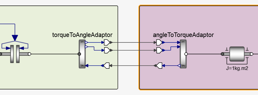
As previously mentioned, the line connecting the two Modelica blocks is a representation of a proper “physical” connection that, in this case, is carrying two underlying numerical signals: the rotation angle and the torque. You now need to expose these signals to end up having only numerical connections at the interface.
The Modelica Standard Library offers dedicated adapters to be picked depending on the physical domain of the model.
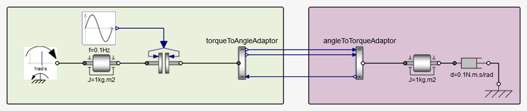
These adaptors add directionality to the connection. On the Engine subsystem, the TorqueToAngleAdaptor provides the rotational angle (and its derivative) as output, and the Load subsystem takes angle as input and provides torque as output, thus forming a perfect pair.
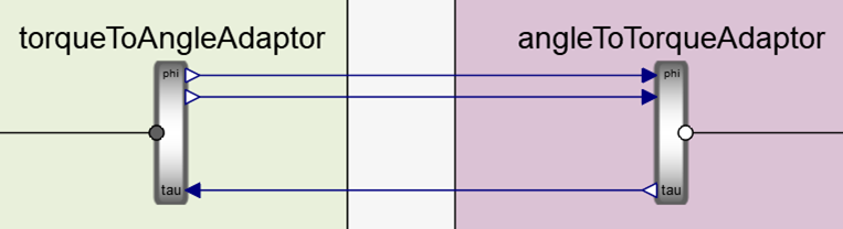
Although the model could run perfectly fine even by switching sides (AngleToTorque on the left and TorqueToAngle to the right), it is generally preferred to let the main co-simulation framework hold the rotation angle.
The augmented number of connection lines between the two subsystems reflects the internal number of signals passed through the (single) original Modelica connection, while the color is now stating that these signals are numerical Modelica signals. However, a further conversion is needed from numerical Modelica to numerical Activate signals.
From Modelica to Twin Activate Connections
Add FromModelica and ToModelica components to the model.
To convert from Modelica to Twin Activate numerical signals, the pair of FromModelica and ToModelica components need to be used. You can find these in but they are also automatically added whenever a link is created between these two types of entities.
These thinner black lines passing the boundaries clearly tell you that the data transferred is of a Twin Activate numerical type. These components have an evident direction.
Export an FMU
Wrap the load subsystem into a super block and export as FMU.
It is now possible to wrap the “load” subsystem into an FMU.
First, wrap it into a super block whose perimeter will be the one of the equivalent FMU. It is important to go through this step only when the connections passing the super block boundaries are purely of Twin Activate signal type.
Select from the menu ribbon. You can also right-click on the super block and select Code Generation and Export. Select FMU as the Target, and then click Generate.
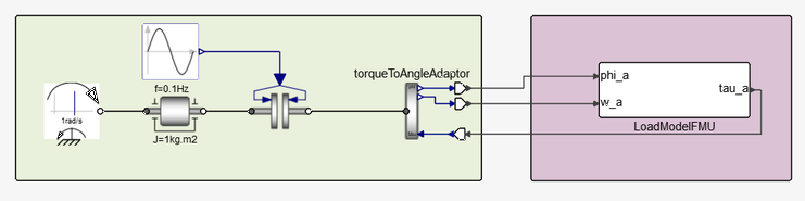
Import an FMU
A similar setup is required while importing an FMU. The leftmost part (the “Engine” subsystem) is identical, while the rightmost is simply replaced by an FMU Twin Activate block (in the palette ). The very same connections apply.
Which Side Sets the State?
This is a discussion of the importance of only one side setting the state of a component or its rigidly-connected neighbors.
The model below shows a very common issue in models built to work as FMUs: the two masses, rigidly connected together, have their positions set by two different sources.
The Modelica compiler will throw an error even if the two position sources have the same numerical values. This is typically signaled by an error of the type “system is overdetermined.”
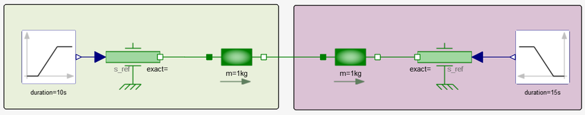
Although it is clear in a very trivial model, it might come unnoticed in more complex cases, especially when either one of the two subsystems is wrapped inside an FMU.
It is important to make sure that only one of the two sides sets the state of a component or of its rigidly-connected neighbors. Any model that breaks this rule will inevitably incur convergence issues.
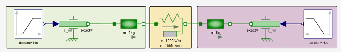
To overcome the problem of an overdetermined state, you might soften the coupling between the two subsystems before replacing one part with an FMU. You can add a spring-damper for the mechanical domain, an LC circuit in the electrical domain, etc. In this case, the binding happens through forces and torques (for the mechanical domain) or currents (for the electrical domain) instead of, respectively, position and rotations, or voltages. This solution, however, should be taken only as last resort, for example, when you cannot modify the models.
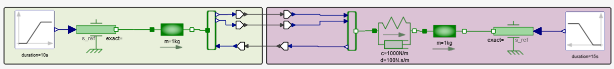
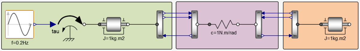
アドバンスト:複数のサブシステム
場合によっては、1つのFMUを複数のサブシステムにリンクする必要があります。
この例では、2つの異なるケースについて示します。前者は剛結合の場合、後者は軟結合の場合です。
最初のケースは、サブシステムの因果関係は、固有の方向性を特定できるようなものです。1番左のブロックは、2番目のインターフェイスの位置を設定し、2番目のブロックは3番目のインターフェイスの位置を設定します。こうすることで、サブシステムの状態を過剰に決定してしまうリスクを回避することができます。
一方、2番目のケースでは、左端と右端のブロックの両方が、中央のブロックに対する位置情報を提供します。これは、中央のブロックが2つの横方向のブロック間の軟結合を提供することにより可能になります。