Wall
Create a surface that extends from the part to the binder, to aid in stretching and forming.
-
Click the Addendum Extend icon.

-
Select the Wall tool on the secondary ribbon.

The guide bar and control panel appear.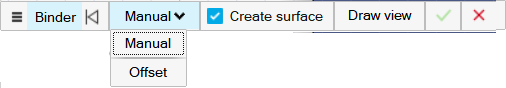

-
Select points to create the wall:
To Do this Manually select points (default) - Select the binder.Note: A sketch plane for the wall is created and visualized as a blue square.Note: In the guide bar, by default, Create surface is selected so that a surface is automatically created. If you don’t want to automatically create a surface, deselect Create surface.
- Click to add points for the wall.
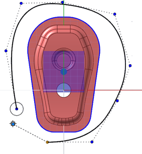
- To close the wall, drag the first and last points together. The surface is automatically created when the wall curve is closed.
- To keep the wall curve open, place the points, then
right-click to confirm.Note: If the wall overlaps the part, a red line will appear.
Automatically create points - Select the binder.Note: A sketch plane for the wall is created and visualized as a blue square.
- In the guide bar, select Offset mode.
- Configure the Offset mode
guide bar.
 Note: In the guide bar, by default, Create surface is selected so that a surface is automatically created. If you don’t want to automatically create a surface, deselect Create surface.
 - Choose an edge selection method, then select the
edge(s) you would like to create the wall around.
- Chain Selection: Selects an edge and all connected edges.
- Tangent Selection: Selects an edge and the tangent edge.
- Single Selection: Selects one edge at a time.
- Enter a value for the wall Offset.
- Right-click to auto-create the points.
The points for the wall appear around the selected edge(s).
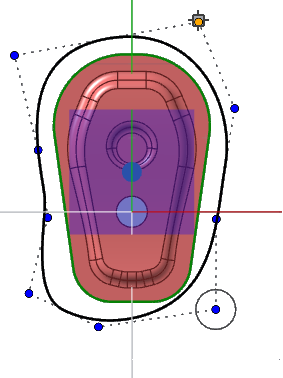
- Drag the points to adjust
them.Note: If the wall overlaps the part, a red line will appear.
- Select +/- to invert the offset shape.
- Select the binder.
- Optional:
Edit the wall.
To Do this Reposition a point - Drag a point.
- Click a point, click the chevron, enter the x, y, and z coordinates, and then press Enter.
Delete a point Click a point, and then press Alt+D. Add a point While holding down Alt, click or drag the desired additional point  .
. Smooth the curve Click a point, and then click the Smooth icon  .
.Sharpen the curve Click a point, and then click the Cusp icon  . Note: Only cusp curves have the option to change the radius.
Click a point, click the chevron, enter a Radius, and then press Enter.
Open the curve Click a point, and then click the Open the curve hereicon  .Note: The curve needs to be closed before you can open it.
Add weight to a point Click a point, click the chevron, enter a Weight, and then press Enter. Note: Add weight to a control point to give it greater influence over the shape of the curve.Extend the wall In the modeling window, drag the white arrows. Edit the draft angle In the Control Panel, enter a value for Wall draft angle. Invert the direction of the wall In the Control Panel, turn on Invert draft. Reposition the wall sketch plane In the modeling window, select the sketch plane, and then drag the arrow.