Mounting Coordinate List
You can extract the component coordinate list for chip mounter programming from the design.
-
Click the selection box of Origin Position to select the origin position.
Note: You can also click Origin to select the origin of the PCB.
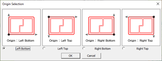
Figure 1.- Attribute Item List: Select the component attributes to be extracted.
- Selected Item List: The selected attributes to be extracted.
- Select/Unselect: Move selected items from/to the attribute item list and selected item list.
- Change order: Change the extraction order of the selected item list.
- Mount Type: Define the mount type for the selected components. Components not set up will be set to the opposite type. For example, if SMD type is defined for selected components, remainders are defined as DIP type.
- Exception: Select the component database file that is excluded. Up to two files are available for exception.
- Control Menu: Control menus are the same as the Mounting Parts List function.