
Define Hot Runner
Identify existing geometry as hot runners and define the hot runner system.
Create a runner system geometry before defining it as a hot runner system.
-
Click the Select Hot Runner icon, then select parts in
the model geometry to designate them as part of the hot runner system.

-
Use the guidebar to select between an insulated or heated runner, set a heated
runner's temperature, and if desired, enable valve gates.

-
Optional: Click Select Valve Gates to designate one or
more valve gates.
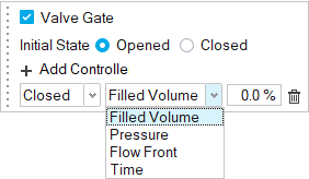
- Select a gate. Enable the Valve Gate option in the microdialog.
- Set the gate's initial state to opened or closed, and add controllers to change the gate's state as needed.
Note:- Two or more gates are required for this option.
- At least one gate must start in the opened state.
- Each valve gate must be designated individually.
- You may add more than one control to a single gate.
- You can set a gate's state to change based on filled volume, pressure at a selected point in the cavity, flow front position, or elapsed time.
Control Option Description Note Filled Volume Defines the control as a percentage of the total material volume. Enter the percentage. Pressure Defines the control as the pressure at a specified point on the model. - Enter the pressure.
- Click the point icon
 , then click a point on
the model where you want the specified pressure to
control the valve gate.
, then click a point on
the model where you want the specified pressure to
control the valve gate.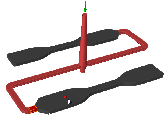
Flow Front Defines the control as the material flow at a specified point on the model. Click the point icon , then click a point on the
model where you want the flow front to control the valve
gate.Time Defines the control as a duration of time. Enter the time in seconds.