
Automatically Create Runner System
If your model geometry does not include a runner system, you can create a virtual runner system automatically with the Create Runner tool.
Location: Molding tab, Advanced
mode, Runner System secondary ribbon

After you define the required number of part cavities for your model,
use the Create Runner tool to generate the entire runner system for the model including
the gate, runner, sprue and injection point.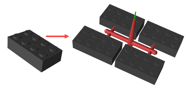
Note: The Create Runner tool does not support multiple
gates. Use a single gate only.
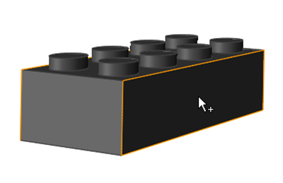
- Designate a part cavity in your model geometry.
-
Click the Runner System icon.

-
Click the Create Runner icon on the secondary ribbon.

-
Enter the parameters for your part(s) and runner system on the Create Runner
microdialog.
Parameter Description Num. of cavity Set the number of part cavities to fill. Keep the default of 1 or select 2, 4, or 8 from the dropdown menu. Section Select Circular or Square for the shape of the runner. 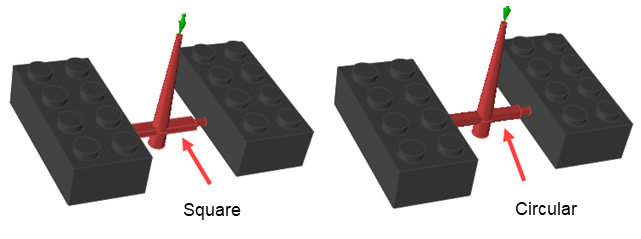
-
Click Injection Point and select the surface of the part
where you want to attach the gate of the runner system.
Note:
- If your part already includes a designated gate, you do not need to select a surface. The runner will automatically attach to the existing gate.
- The runner system's configuration will be based on the direction selected with the Mold Opening Direction tool
Inspire Mold automatically generates the runner system for your model.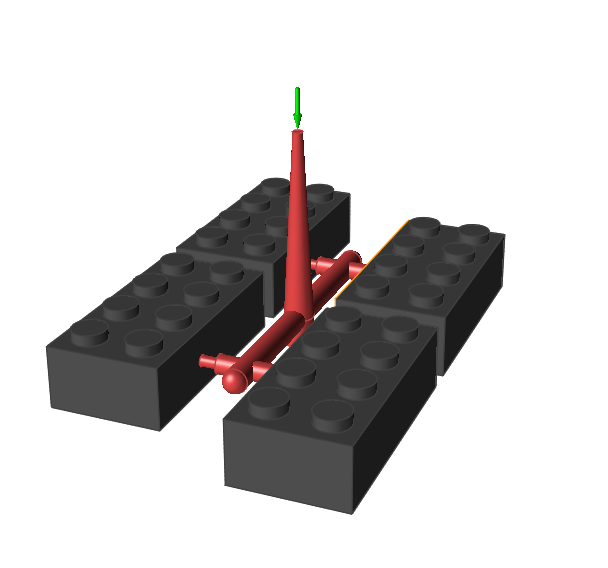
- Select a runner system component to change its dimensions. To change the minimum distance between part cavities, select a part.