
Part Cavity
Use the Part Cavity tool to designate, automatically detect, and reorient the part cavities in your model geometry.
Location: Molding ribbon

Note: In Quick mode, the Auto-Configure
Components satellite icon is not present.
Designate a Cavity
Define the part cavities, material type, polymer, and temperature for the molding simulation.
Note: You need to designate a part cavity before performing any other
operation.
-
On the Molding Part icon, click Designate
Part Cavity.

-
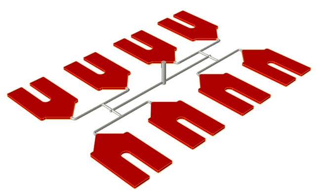
Select the part cavity in your model. If your model contains more than one part
cavity, select them all.
The selected parts are displayed in red.
-
Use the microdialog options to define the material, polymer, and
temperature.
Option Description Note 
Click the View Materials button to examine
the material's thermal, rhealogical, mechanical, PVT and
fiber properties.- You can modify an existing material in the Materials dialog, save it with a new name, and access it from the My Materials tab.
- You can download additional materials from the Altair Material Data Center, save them locally, and import them into My Materials.
Select a material type. 
Select from common polymers of your chosen material type. 
Validate the material. Generate a .pdf file with relevant data on the material, including thermomechanical properties, viscosity, temperature dependence, and equation of state.
Mold Opening Direction
Reorient the mold's opening direction with respect to the part.
-
On the Molding Part icon, click Mold Opening
Direction.

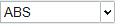
The Demolding window appears, along with a gray frame indicating the plane and direction of the mold opening. The mold will open along the Z-axis by default. Surfaces likely to bind with the mold, making demolding difficult, are highlighted in red: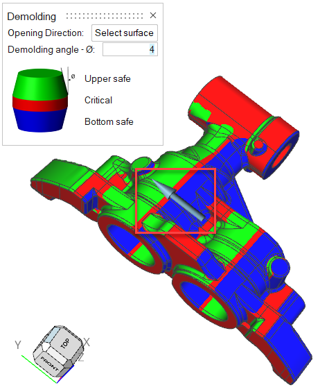
-
Click the Select surface button and select the face of
the part that it is perpendicular to the optimal mold opening direction. In the
example below, the selection is outlined in yellow.
The frame reorients with the selected face perpendicular to the mold opening direction.Note: Surfaces at an angle from the mold opening direction smaller than the demolding angle are in a critical orientation to the mold, and may adhere to the mold during the demolding process. Critical surfaces appear in red.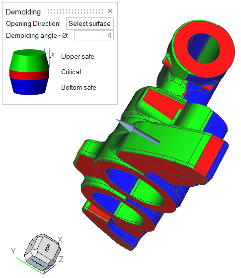
-
Set the demolding angle.
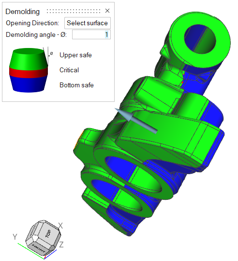 Note: The Demolding angle field defaults to 4 degrees, though for most applications, a tolerance of 2 degrees or less is sufficient.