Tutorial Level: Beginner Learn how to use the ribbon, mouse controls, view controls, and how to create a force and
draw direction.
In this lesson you will learn about:
The ribbon
Importing files
View controls
Showing and hiding parts
Creating and editing forces
Creating and editing draw directions
Explore the Ribbon
Start Inspire.
The ribbon across the top of the application displays all of the tools
available in Inspire. Click on the tabs at the top of the
ribbon to switch between the various menus and ribbons.
Each icon on the ribbon provides access to one or more tools. As you mouse over
an icon, the individual tools glow with a blue border.
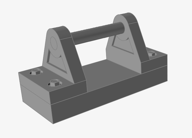
Double-click the dual bracket.stmod file to load it in the
modeling window.
If not already visible, press F2 to open the Model
Browser.
Click on the Unit System Selector in the lower right
corner of the modeling window, and set the display units to MKS (m kg
N s).
Use the View Controls
Pan the model by holding down the right mouse button
while dragging the mouse. Press the C key and click a
point on the model to center it around that point.
Rotate the model by holding down both the Shift key and
the right mouse button while dragging the mouse. This
rotation method is called turntable rotation and is useful if your
model's vertical direction is aligned with the z-axis.
Now hold down the middle mouse button while dragging the
mouse. This is called trackball rotation and is useful for tumbling
your model in any direction. Press the N key to rotate
the model to the closest principal axis.
Use the scroll wheel to zoom centered on the mouse
cursor. To zoom around the center of the modeling window, press the
Ctrl + Shift keys and drag the right mouse
button vertically.
The view controls are located in the lower left corner of the modeling window.
Click the icon in the lower left corner of the modeling window or press the
F key to fit the entire model in the view.
Note: If parts are selected rather than the entire model, clicking the icon will zoom in on the selected parts.
Clicking the icon again will zoom out to show the entire model. Try pressing
F repeatedly with different parts selected to see
the effect.
Note: To customize your mouse controls to mimic a different application, select
File > Preferences to open the Preferences window. Then
select Mouse Controls > Presets and choose an application
from the drop-down list.
Show and Hide Parts
Click the Show/Hide icon in the lower left corner of the modeling window.
Hover over a part. The mouse cursor will change to ,
indicating that you are in show/hide mode.
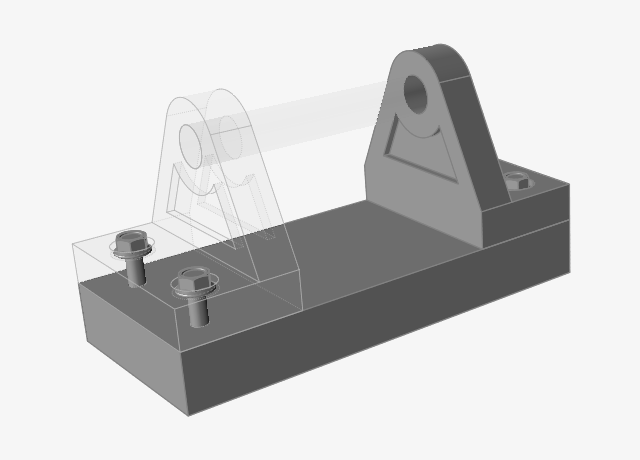
Left-click one or more parts in the modeling window. The parts turn transparent
as you select them and are grayed out in the Model Browser.
Right-click and mouse through the check mark or double-right-click to exit
show/hide mode. The selected objects are hidden in the modeling window.
To show parts that are hidden, select the Show/Hide tool again.
Click on a transparent part while holding down the Shift
key. While the Shift key is pressed, the cursor changes
to .
Click on the remaining transparent parts, then right-click and mouse through
the check mark or double-right-click to exit show/hide mode.
Using keyboard shortcuts is another way you can show, hide, or isolate
parts.
Press the A key to show all parts, or to hide all
visible, unselected parts.
Press the H key to hide selected parts.
Press the I key to isolate selected parts.
Press the R key to reverse the selection (hide
all visible parts and show all hidden parts).
Apply a Force and Draw Direction
Select one of the brackets and press the I key to
isolate it.
Move the mouse cursor over the front face of the bracket and left-click to
apply a distributed force.
A microdialog appears when creating or editing forces. Enter 45
N in the text field and click the +/-
button to change the direction of the force.
Right-click and mouse through the check mark to exit, or double-right-click.
Apply a draw direction constraint to the bracket by left-clicking the
Draw Directions tool on the Shape
Controls icon. (You'll learn more about draw directions in later
tutorials.)
Click the Single Draw tool on the secondary
ribbon.
Left-click the bracket. A blue plane appears with four corner arrows pointing
toward the face of the bracket, indicating the draw direction (the direction the
mold will be pulled away from the part).
Right-click and mouse through the check mark to exit, or double-right-click.
Edit the Force and Draw Direction
Once objects have been created, it is easy to create more
objects of the same type or edit those objects by double-clicking on them in the
modeling window.
Double-click the blue plane to edit the draw direction. You are now in edit
mode, and a microdialog appears.
Click one of the gray planes to activate it and change the orientation of the
draw direction.
Right-click and mouse through the check mark to exit, or double-right-click.
Double-click the red force arrow on the front face. You are now in edit mode,
and a microdialog reappears.
You can edit the force by entering a magnitude in the text field, or change its
direction by pressing the +/-, X, Y, Z buttons.
Note: To quickly edit an integer value in a microdialog, highlight any digits in
the number and use the scroll wheel on the mouse.
You can also create more forces by selecting another face, as shown
below:
Right-click and mouse through the check mark to exit, or double-right-click.


 icon next to the ribbon tabs to create a custom
ribbon.
icon next to the ribbon tabs to create a custom
ribbon.


 icon in the lower left corner of the modeling window or press the
F key to fit the entire model in the view.
Note: If parts are selected rather than the entire model, clicking the
icon in the lower left corner of the modeling window or press the
F key to fit the entire model in the view.
Note: If parts are selected rather than the entire model, clicking the
 icon in the lower left corner of the modeling window.
 ,
indicating that you are in show/hide mode.
,
indicating that you are in show/hide mode.

 .
.


 Tip: To find and open a tool, press Ctrl+F. For more information, see Find and Search for Tools.


