
/TRANSFORM/POSITION
Block Format Keyword Defines 3 starting points and 3 ending points for transformation and rotation.
Format
| (1) | (2) | (3) | (4) | (5) | (6) | (7) | (8) | (9) | (10) |
|---|---|---|---|---|---|---|---|---|---|
| /TRANSFORM/POSITION/transform_ID/unit_ID | |||||||||
| transform_title | |||||||||
| grnd_ID | node_ID1 | node_ID2 | node_ID3 | node_ID4 | node_ID5 | node_ID6 | sub_ID | ||
| X_point_1 | Y_point_1 | Z_point_1 | |||||||
| X_point_2 | Y_point_2 | Z_point_2 | |||||||
| X_point_3 | Y_point_3 | Z_point_3 | |||||||
| X_point_4 | Y_point_4 | Z_point_4 | |||||||
| X_point_5 | Y_point_5 | Z_point_5 | |||||||
| X_point_6 | Y_point_6 | Z_point_6 | |||||||
Definition
| Field | Contents | SI Unit Example |
|---|---|---|
| transform_ID | Transformation identifier. (Integer, maximum 10 digits) |
|
| unit_ID | Unit identifier. (Integer, maximum 10 digits) |
|
| transform_title | Transformation title. (Character, maximum 100 characters) |
|
| grnd_ID | Node group identifier. 3
(Integer) |
|
| node_ID1 | Starting node
1. (Integer) |
|
| node_ID2 | Starting node
2. (Integer) |
|
| node_ID3 | Starting node
3. (Integer) |
|
| node_ID4 | Ending node
4. (Integer) |
|
| node_ID5 | Ending node
5. (Integer) |
|
| node_ID6 | Ending node
6. (Integer) |
|
| sub_ID | Submodel identifier. (Integer) |
|
| X_point_1 | X coordinate of point 1. (Real) |
|
| Y_point_1 | Y coordinate of point 1. (Real) |
|
| Z_point_1 | Z coordinate of point 1. (Real) |
|
| X_point_2 | X coordinate of point 2. (Real) |
|
| Y_point_2 | Y coordinate of point 2. (Real) |
|
| Z_point_2 | Z coordinate of point 2. (Real) |
|
| X_point_3 | X coordinate of point 3. (Real) |
|
| Y_point_3 | Y coordinate of point 3. (Real) |
|
| Z_point_3 | Z coordinate of point 3. (Real) |
|
| X_point_4 | X coordinate of point 4. (Real) |
|
| Y_point_4 | Y coordinate of point 4. (Real) |
|
| Z_point_4 | Z coordinate of point 4. (Real) |
|
| X_point_5 | X coordinate of point 5. (Real) |
|
| Y_point_5 | Y coordinate of point 5. (Real) |
|
| Z_point_5 | Z coordinate of point 5. (Real) |
|
| X_point_6 | X coordinate of point 6. (Real) |
|
| Y_point_6 | Y coordinate of point 6. (Real) |
|
| Z_point_6 | Z coordinate of point 6. (Real) |
Comments
- Three starting and
three ending points, define a transformation which allows rotation and
translation. The starting and ending points can be defined using nodes or
coordinates.
Figure 1. 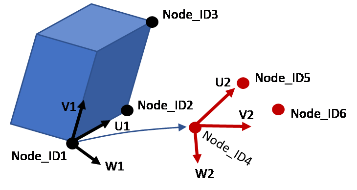
- If the six node_ID are defined, the transformation is defined using nodes and the coordinate point input is not used. If the node_ID input is blank, the X, Y, Z coordinate point input is used to define the transformation.
- Caution, transforms applied to node groups via grnd_ID only transform the nodal coordinates. Material directions for orthotropic materials and boundary conditions such as initial velocity, imposed movement are not transformed. To provide a complete transformation, the /TRANSFORM card should reference a //SUBMODEL and not a node group.
- A transformation cannot apply to a node group and a submodel at the same time.
- If the transformation is done on a submodel, all the options of this submodel are transformed.
- A node cannot be transformed both in a submodel and a node group.