/PROP/TYPE18 (INT_BEAM)
Block Format Keyword Describes the integrated beam property set. This beam model is based on Timoshenko theory and takes into account transverse shear strain without warping in torsion.
It can be used for deep beam cases (short beams). Beam section and position of integration points can be either used as predefined or prescribed directly.
Format
| (1) | (2) | (3) | (4) | (5) | (6) | (7) | (8) | (9) | (10) |
|---|---|---|---|---|---|---|---|---|---|
| /PROP/TYPE18/prop_ID/unit_ID or /PROP/INT_BEAM/prop_ID/unit_ID | |||||||||
| prop_title | |||||||||
| Isect | Ismstr | ||||||||
| dm | df | ||||||||
| NIP | Iref | Y0 | Z0 | ||||||
| (1) | (2) | (3) | (4) | (5) | (6) | (7) | (8) | (9) | (10) |
|---|---|---|---|---|---|---|---|---|---|
| Yi | Zi | Area | |||||||
If Isect > 0, add following 2 lines
| (1) | (2) | (3) | (4) | (5) | (6) | (7) | (8) | (9) | (10) |
|---|---|---|---|---|---|---|---|---|---|
| NITR | L1 | L2 | |||||||
| Blank Line | |||||||||
| (1) | (2) | (3) | (4) | (5) | (6) | (7) | (8) | (9) | (10) |
|---|---|---|---|---|---|---|---|---|---|
Definition
| Field | Contents | SI Unit Example |
|---|---|---|
| prop_ID | Property
identifier (Integer, maximum 10 digits) |
|
| unit_ID | Unit Identifier (Integer, maximum 10 digits) |
|
| prop_title | Property
title (Character, maximum 100 characters) |
|
| Isect | Section type. 6
(Integer) |
|
| Ismstr | Small strain option flag.
(Integer) |
|
| dm | Beam membrane
damping. Default = 0.00 (Real) |
|
| df | Beam flexural
damping. Default = 0.01 (Real) |
|
| NIP | Number of integration
points (subsections). Only for Isect =0; otherwise, NIP=0. (Integer) |
|
| Iref | Subsection center
reference flag. Only for Isect =0.
(Integer) |
|
| Y0 | Local Y coordinate of the
section center. Only for Isect =0. (Real) |
|
| Z0 | Local Z coordinate of the
section center. Only for Isect =0. (Real) |
|
| Yi | Local Y coordinate of the
integration point. (Real) |
|
| Zi | Local Z coordinate of the
integration point. Only for Isect =0. (Real) |
|
| Area | Area of the subsection.
Only for Isect =0. (Integer) |
|
| NITR | Option for integration
points in predefined section for
Isect >
0. 6. (Integer) |
|
| L1 | First size of the
predefined section for
Isect >
0. 6 (Real) |
|
| L2 | Second size of the
predefined section for
Isect >
0. 6 Default = L1 (Real) |
|
| Rotation DOF code of nodes
1 and 2 (see detail input below). (6 Booleans) |
Detail of Rotation DOF Input Fields for Nodes 1 and 2
| (1)-1 | (1)-2 | (1)-3 | (1)-4 | (1)-5 | (1)-6 | (1)-7 | (1)-8 | (1)-9 | (1)-10 |
|---|---|---|---|---|---|---|---|---|---|
Definition
| Field | Contents | SI Unit Example |
|---|---|---|
| = 1 Rotation DOF about X
at node 1 is released. (Boolean) |
||
| = 1 Rotation DOF about Y
at node 1 is released. (Boolean) |
||
| = 1 Rotation DOF about Z
at node 1 is released. (Boolean) |
||
| = 1 Rotation DOF about X
at node 2 is released. (Boolean) |
||
| = 1 Rotation DOF about Y
at node 2 is released. (Boolean) |
||
| = 1 Rotation DOF about Z
at node 2 is released. (Boolean) |
Example 1 (Integrated Beam)
#RADIOSS STARTER
#---1----|----2----|----3----|----4----|----5----|----6----|----7----|----8----|----9----|---10----|
/UNIT/2
unit for prop
                  Mg                  mm                   s
#---1----|----2----|----3----|----4----|----5----|----6----|----7----|----8----|----9----|---10----|
#-  2. MATERIALS:
#---1----|----2----|----3----|----4----|----5----|----6----|----7----|----8----|----9----|---10----|
/PROP/TYPE18/4/2
Integrated beam - bXh=10X10 with 4 integration points (subsections)
#    Isect   Ismstmr
         0         0
#                 dm                  df
                   0                   0
#      NIP      Iref                  Y0                  Z0
         4         1                   0                   0
#                  Y                   Z                Area
                 2.5                 2.5                  25
                 2.5                -2.5                  25
                -2.5                 2.5                  25
                -2.5                -2.5                  25
# OmegaDOF
   000 000
#---1----|----2----|----3----|----4----|----5----|----6----|----7----|----8----|----9----|---10----|
#ENDDATA
/END
#---1----|----2----|----3----|----4----|----5----|----6----|----7----|----8----|----9----|---10----|
Example 2 (Integrated Beam)
#RADIOSS STARTER
#---1----|----2----|----3----|----4----|----5----|----6----|----7----|----8----|----9----|---10----|
/UNIT/2
unit for prop
                  Mg                  mm                   s
#---1----|----2----|----3----|----4----|----5----|----6----|----7----|----8----|----9----|---10----|
#-  2. MATERIALS:
#---1----|----2----|----3----|----4----|----5----|----6----|----7----|----8----|----9----|---10----|
/PROP/TYPE18/4/2
Integrated beam  - 4 integration points in predefined section bXh=10X10
#    Isect   Ismstmr
         1         0
#                 dm                  df
                   0                   0
#      NIP      Iref                  Y0                  Z0
         0         1                   0                   0
#     NITR                            L1                  L2
         2                            10                  10

# OmegaDOF
   000 000
#---1----|----2----|----3----|----4----|----5----|----6----|----7----|----8----|----9----|---10----|
#ENDDATA
/END
#---1----|----2----|----3----|----4----|----5----|----6----|----7----|----8----|----9----|---10----|
Comments
- Small strain formulation is activated from time t=0, if Ismstr =1. It may be used for a faster preliminary analysis because is constant, but the accuracy of results is not ensured.
- If Ismstr =1, the
strains and stresses which are given in material laws are engineering strains
and stresses. Time history output returns true strains and stresses.
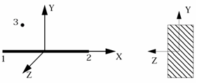
Figure 1. - The cross-section of the element is
defined using up to 100 integration points (Figure 2). The element properties of the cross-section,
that is, area moments of inertia and area, are computed by Radioss as:
(1) (2) (3) - It can be used for deep beam cases (short beams). The use of several
integration points in the section allows to get an elasto-plastic model in which von
Mises criteria is written on each integration point and the section can be partially
plastified contrary to the classical beam element (TYPE3).
Compatible with material LAW1, LAW2, and LAW36. However, as the element has only one
integration point in its length, it is not recommended to use a single beam element
per line of frame structure in order to take into account the plasticity progress in
length, as well as in depth.
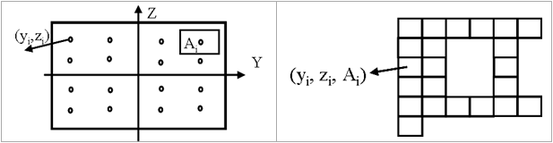
Figure 2. Cross-section Definitions in the Integrated Beam - For rectangular section: L1 is the rectangular size in Y-direction of the local beam coordinates system and L2 is the rectangular size in Z-direction. For circular section: L1 is the radius.
- Predefined cross-sections are
available (circular or rectangular). Number of integration points in the section
is prescribed via NITR depending on
Isect and the chosen
quadrature:
- For Isect =
1 and 2. Integration points are
distributed uniformly across the section according to the section type
and NITR.
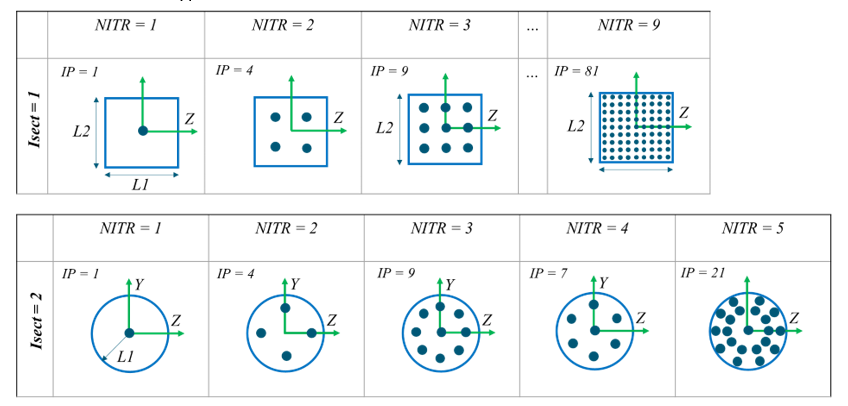
Figure 3. - For Isect =
3. The section is rectangular, the distribution of
the integration points corresponds to the Gauss-Lobatto quadrature with
points on the edge. IP =
NITR*NITR. The maximum
NITR possible is 9 corresponding to 81
integration points.
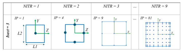
Figure 4. - For Isect =
4. The section is circular. The distribution of the
integration points radially corresponds to Gauss-Lobatto quadrature with
points on edge. Three options: NITR =
1, NITR = 17
and NITR = 25. Here the number of
integration points is equal to NITR.
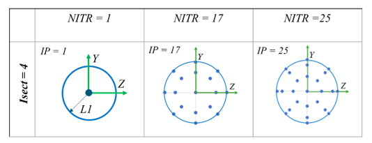
Figure 5. - For Isect =
5. The section is circular. Three options:
NITR = 1,
NITR = 9 and
NITR = 17. Here the number of integration
points is equal to NITR.
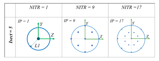
Figure 6.
- For Isect =
1 and 2. Integration points are
distributed uniformly across the section according to the section type
and NITR.