
Non-Symmetric Interface (/INTER/TYPE5)
This interface is used to simulate impacts between a main surface and a list of secondary nodes.
The main surface mesh has to be regular with a good aspect ratio. It is not allowed to put the secondary node on the main surface. It works only with main segments connected to solid or shell elements. One use of this interface is to replace rigid wall. Replacing a rigid wall with interface TYPE5 will allow you to simulate rigid body impacts.
With interface TYPE5, a gap is used to determine contact between a node and a surface. This gap is user-defined and is located on the side normal to the surface. It is recommended to use a small or zero gap.
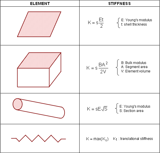
When contact is detected, an elastic spring is added and the spring stiffness is calculated using material and geometric properties of the main segment only. For stability reason, a stiffness scale factor of 0.2 is applied to the main side stiffness. It is strongly advised not to modify this factor unless the main side is very soft compared to the secondary side. If that is the case, it is recommended to use the ratio of the greater elastic modulus over the lower one as stiffness scale factor.
The main drawback of interface TYPE5 is that contact cannot occur on both sides of the main segment. For a problem with large rotations (usually the case in a crash analysis), contact is likely to occur on the wrong side of the surface; therefore, penetration will not be detected. Consequently, for a complex contact problem, a good understanding of the impact is necessary prior to the simulation to properly define normal surfaces.
Another important drawback is that a node is not allowed to be a secondary node and part of a main segment. Therefore, auto-contact cannot be simulated through the use of interface TYPE5.