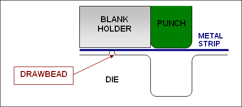
Interface TYPE8 is used to simulate drawbeads. This interface is mainly used in the process
industry to model metal forming. Drawbeads are
used to prevent the metal strip from sliding
during the stamping process. Figure 1. Stamping Process
The modeling of the drawbeads using interface TYPE8 consists in defining a line of secondary
nodes and a main surface. The set of secondary nodes must be sorted since the input force is
a force per unit length, and the length is computed as the distance between two successive
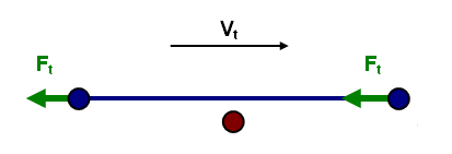
secondary nodes. As soon as a secondary node projects onto a main surface, a tangential
force is applied to all main nodes to counter their tangential velocity (Figure 2).
Consequently the metal strip does not slide. Figure 2. Drawbead Force
Note: The global force acting on the main surface cannot be greater than the drawbead
force per unit length (user-defined) multiply by the distance of two successive secondary
nodes. In that case, sliding of the metal strip will occur.
Common Problem
In case the drawbead is not continuous, it is necessary to create several TYPE8 interfaces, one
interface for each continuous drawbead. Otherwise,
the drawbead force can be far too high between two
successive nodes that are not part of the same
continuous drawbead.
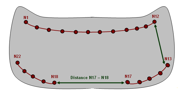
Figure 3
illustrates this point. The grey part could be a
car hood, and three drawbeads are needed during
the stamping process. If only one interface TYPE8
is created, as the drawbeads are not continuous,
the distance between node N17 and N18 is much
larger than the average distance between two
successive nodes. Therefore, the drawbead force
applied to nodes N17 and N18 could be too high,
leading to unrealistic deformation in these
areas. Figure 3. Example of Hood Stamping