
RD-V: 0220 Foam Material (LAW70)
Foam material law under compression and tensile load cases.
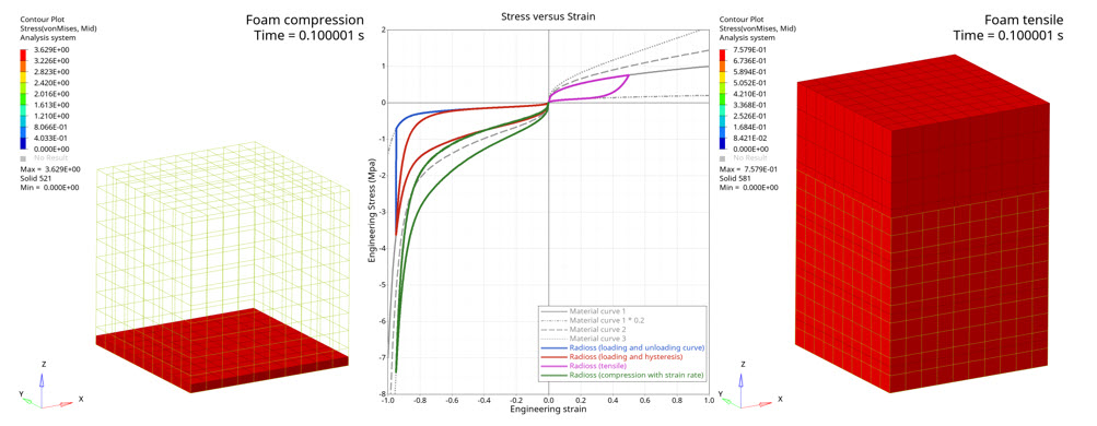
The analysis shows the behavior of the foam material /MAT/LAW70 under compression and tensile load cases.
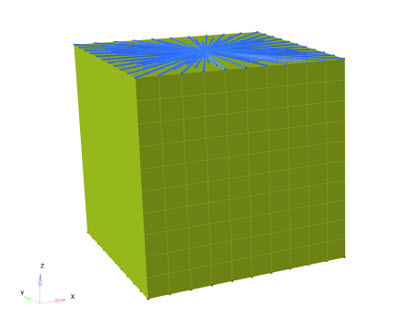
A cube (100mm*100mm*100mm) is modeled with solid elements.
- With compression load case for a material without strain rate dependency and unloading curve
- With compression load case for a material without strain rate dependency and hysteresis parameters
- With tensile load case for a material without strain rate dependency and hysteresis parameters
- With compression load case for a material with strain rate dependency and hysteresis parameters
The reaction force result is extracted from the rigid bodies which model the anchorage and loading condition.
Options and Keywords Used
Input Files
Model Description
Units: Mg, s, mm, MPa
A cube (100mm*100mm*100mm) modeled with solid elements (/PROP/SOLID) and foam material (/MAT/LAW70) is compressed or extended in the vertical direction.
The nodes of the cube top surface are defined in a rigid body (/RBODY) with a vertical imposed displacement defined with a smooth function (/FUNCT_SMOOTH).
The nodes of the cube lower surface are also defined in a rigid body and its main node is clamped using a boundary condition (/BCS).
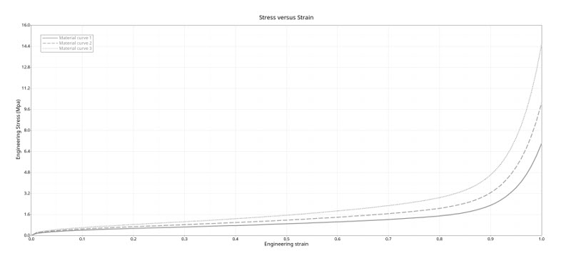
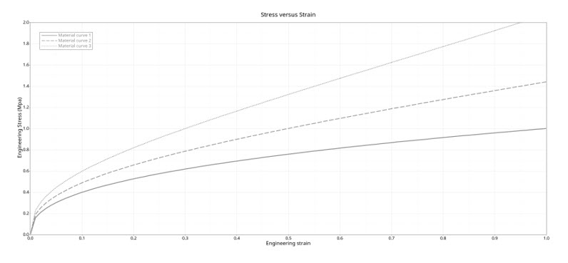
The material is defined with engineering stress versus engineering strain with several curves for the strain rate dependency.
- Model
- Description
- 0220_foam_LAW70_0
- Compression up to 95% of the initial solid block height
- 0220_foam_LAW70_1
- Compression up to 95% of the initial solid block height
- 0220_foam_LAW70_2
- Tensile up to 50% of the initial solid block height
- 0220_foam_LAW70_3
- Compression up to 95% of the initial solid block height
Results
| Stress @ 40% strain during loading phase | Radioss result | Input curve | Difference |
|---|---|---|---|
| 0220_foam_LAW70_0 | -0.7588378906250001 | -0.757144898 | 0.2% |
| 0220_foam_LAW70_1 | -0.7588378906250001 | -0.757144898 | 0.2% |
| 0220_foam_LAW70_2 | 0.6936982421875 | 0.693144843 | 0.1% |
| 0220_foam_LAW70_3 | -1.2752874023437502 | -1.271712685 | 0.3% |
| Stress @20% strain during unloading phase | Radioss result | Input curve | Difference |
|---|---|---|---|
| 0220_foam_LAW70_0 | -0.10638489990234376 | -0.10506111220000001 | 1.3% |
| 0220_foam_LAW70_1 | -0.10643869628906251 | -0.10506111220000001 (*) | 1.3% |
| 0220_foam_LAW70_2 | 0.10709613037109375 | 0.105061112 (*) | 1.9% |
| 0220_foam_LAW70_3 | -0.49272646484375004 | -0.498375326 (*) | 1.1% |
(*) Estimated value from hysteresis value, static and dynamic curves.
The engineering stress versus engineering stress computed from the rigid body force and nodal displacement give results which overlay exactly the input curve from the material.
The unloading behavior with model with the unloading curve (0220_foam_LAW70_0) is less realistic than the model with hysteresis behavior (0220_foam_LAW70_1).