Frequency Response Stress results from the Frequency Response Analysis are used to
calculate the frequency-dependent stress range, which are subsequently used to
calculate fatigue damage based on sweep rate. Here the stress-life (SN) approach is
used for calculating the fatigue life of the component.
The solid element properties are:
Bracket
First order Tetra elements
The shell element properties are:
Skin Surface Near the Fillet Region
First order Tria elements
The material properties are:
MAT1 with MATFAT
Young's Modulus
2.1 x 10⁵ N/mm2
Poisson's Ratio
0.3
Density
7.9 x 10⁻⁹ ton/mm3
Shear Modulus
0.02 N/mm2
MATFAT
Yield Strength
180 MPa
Ultimate Tensile Strength
340 MPa
Fatigue Strength Coefficient
936
First Fatigue Strength Exponent
-0.161907
Limit of Endurance
1 x 1030
Fatigue Limit
1
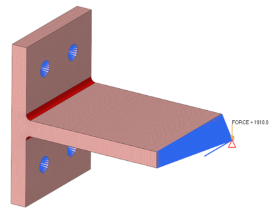
Consists of a simple bracket constrained at the bolting locations and applied a force
in the y direction at the free end on a connected RBE2. There are
three loadcases for this example, Linear Static, Modal Frequency Response Analysis
and Fatigue Loadcase. The stress results from the Frequency Response Analysis are
used to calculate the frequency-dependent stress range and subsequently used for
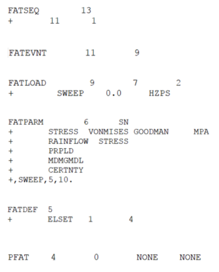
calculating the fatigue damage based on sweep rate.Figure 2. All the Fatigue Cards used for this Analysis
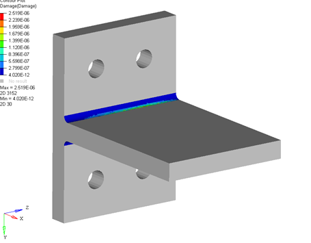
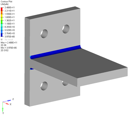
Results
Figure 3. Fatigue Damage Results Figure 4. Fatigue Life Results