OS-E: 0335 Measure Sound Radiation from Impacting Plates
Explicit Analysis of the impacting plates to extract the contact forces and
performing Frequency Response Analysis using these forces as input to study the sound
radiation by the plates.
Model Files
Before you begin, copy the file(s) used in this example to
your working directory.
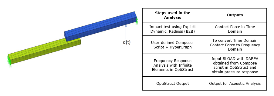
Two plates (Figure 1) are meshed with first order CHEXA element.
Both the plates are constrained at one end in all DOF’s and time dependent load is
applied on upper plate, which causes it to impact with the lower plate. Explicit
Analysis is performed for the setup and contact forces are requested as an
output.Figure 1. Finite Element Model of Impacting Plates with the Boundary
Conditions and Analysis Procedure
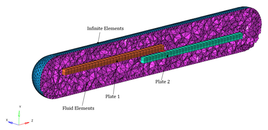
The frequency response setup has a smooth acoustic mesh (in this case a cylinder with
hemispherical faces) around the impact plates. The ends of the acoustic mesh
(surface of the cylinder) have infinite elements. Perform the Frequency Response
Analysis to calibrate the sound radiated by the impacting plates at a distance of
1.5m and 2.5m (location of mic points).Figure 2. FE Setup for Frequency Response Analysis
Material Properties: Polycarbonate (Plates)
Young's modulus
1E+03 MPa
Poisson's ratio
0.4
Density
1E-09 ton/mm3
Material Properties: Air (Acoustic Mesh)
Sound velocity
343000 mm/s
Density
1.2E-12 ton/mm3
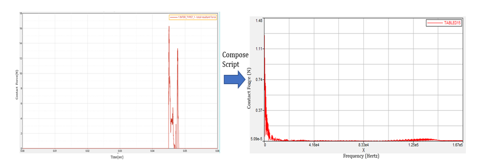
Contact Force Conversion (Time to Frequency Domain)
Contact forces obtained from explicit analysis are in time domain, to convert the
time domain results into frequency domain with help of Compose Script. These frequency dependent forces are fed as
an input for Frequency Response model where the sound radiation is checked, due to
this impact phenomenon.Figure 3. Contact Force Time to Frequency Domain Conversion
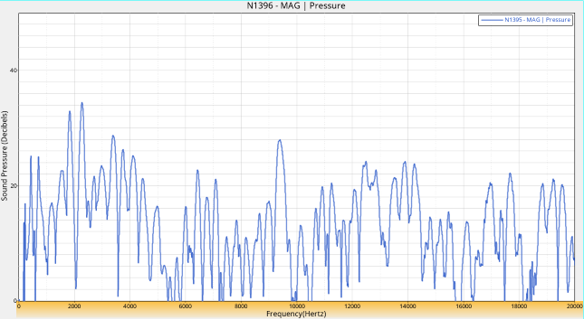
Results
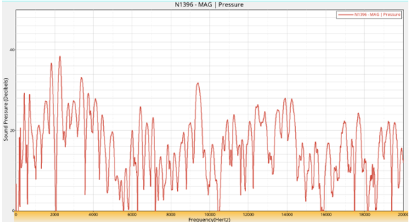
Figure 4. Sound Pressure Level at a Mic Point(N1395) . 2.5m far from the sound source with a maximum of 34.43 DB Figure 5. Sound Pressure Level at a Mic Point(N1396) . 1.5m far from the sound source with a maximum of 38.41 DB