OS-V: 1215 Damage Initiation and Evolution Study, Single Element Model
A model with two single element components, CHEXA8 and CQUAD4, is subjected to pure shear deformation through the application of the enforced displacement (via the SPCD card).
Model Files
Benchmark Model
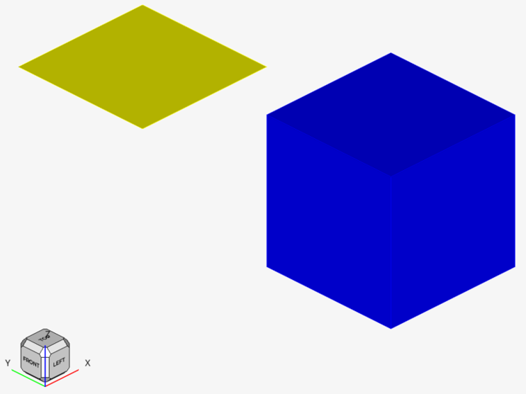
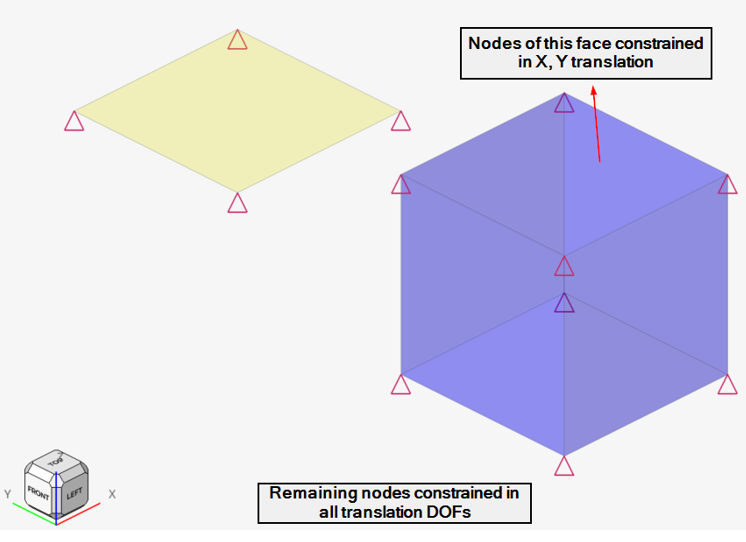
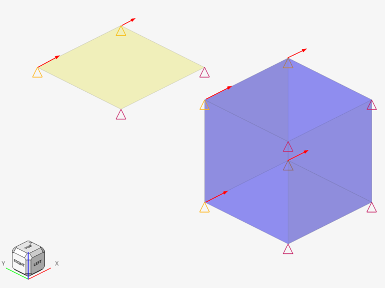
The finite element model, as shown in Figure 1, contains one solid CHEXA and one shell CQUAD4 element. The elements are subjected to dynamic, monotonically increasing shear deformation by application of the enforced displacement (via SPCD card) in the X-direction. All translational DOFs of the model are constrained except the top face of the solid element, which is constrained only in the X- and Y-directions. An enforced displacement in the X direction is applied to one face of the CHEXA8 element and an edge of the CQUAD4 element.
In explicit dynamic analysis, damage criterion is defined with the MATF card, where the MATF material identification number is the same as the corresponding MAT1/MATS1. The INIEVO continuation line in MATF is used to define the damage criterion. Additionally, there are two table IDs defined. The first table (DMGINI) defines the damage initiation, and the second table (DMGEVO) defines the damage evolution.
The DMGINI table defines the damage onset, which is related to the equivalent plastic strain (1st column) at the specific stress state (stress triaxiality, 2nd column) at the specific strain rate (3rd column). In pure shear (which is the case currently), stress triaxiality equals 0.0. It is considered good practice to define the lowest strain rate to be 0.0 for proper interpolation/extrapolation of damage onset at different strain rates. In this example, the model is rate independent as the damage onset values are matching at the two strain rates.
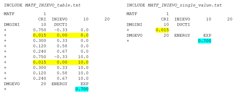
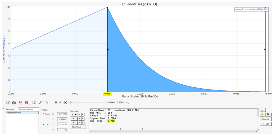
Damage evolution is specified with the DMGEVO card. In this example, the type of evolution is ENERGY and the shape is EXPONENTIAL. The unit of energy is N/m (stress N/m2 multiplied by the length m). Length is related to the plastic displacement at the ultimate failure minus plastic displacement at the damage onset. Plastic displacement is equivalent to the plastic strain multiplied by the element characteristic length. In general, DMGEVO shows mesh dependency, but in this example the characteristic length equals to 1.0. Therefore, plastic displacement and equivalent plastic strain are mutually the same.
Material
- Elastic-plastic Material Properties
- Young's modulus
- 70000
- Poisson's ratio
- 0.33
- Density
- 2.7E-06
- Plastic Properties
- TABLEG entries for stress strain curve
-
Strain Stress 0.0 70 0.015 140.0 - Yield function criterion
- Von Mises
- Hardening rule
- 1 (Isotropic hardening)
- Type of strain
- 1 (Plastic strain used on X-axis)
Results