MV-8500: Use the Truck Library
In this tutorial, you will build a full truck model with a driver, add events to the model, and view the reports.
The purpose of this tutorial is to walk you through the process of how to build a full truck model with advanced drivers and how to add events to the model built.
The new event user interface is supported only for models with advanced drivers. Files can be edited or updated in the event editor. Sixteen event types are supported. To learn more about the events, see Full Vehicle with Driver.
Select Model Type
In this step, you will load the MBD-Vehicle Dynamics Tools preference file and select a model type using the Set wizard library dialog.
In MotionView, models are assembled from libraries of pre-defined systems using the Assembly Wizard. The Assembly Wizard dialog guides you through the assembly process, ensuring that your selections are compatible.
-
Start a new MotionView session.
Figure 1. 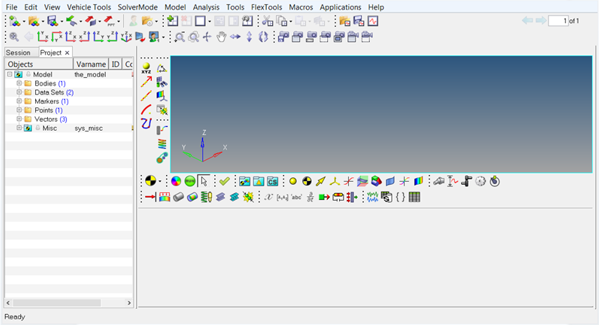
-
From the menu bar, click to open the Preferences dialog.
Figure 2. 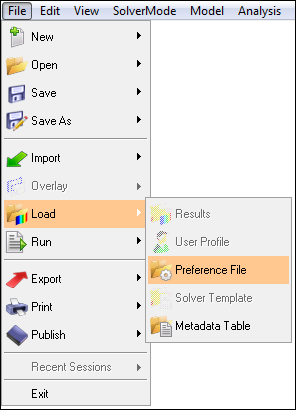
-
Select MBD-Vehicle Dynamics Tools and click
Load.
Figure 3. 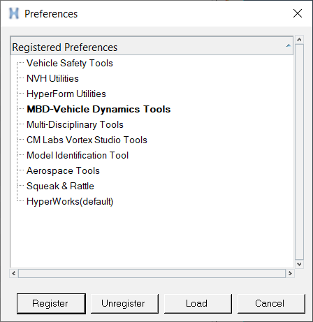
-
Set the required truck wizard paths using the Assembly
Wizard dialog.
-
From the menu bar, click .
Figure 4. 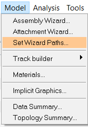 The Set wizard library dialog opens.
 -
From the Wizard library drop-down menu, select
Heavy Truck.
Figure 5. 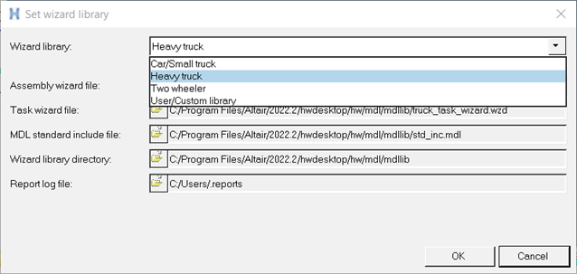
-
From the menu bar, click .
-
From the menu bar, select .
Figure 6. 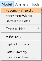
The Heavy truck - Model Type dialog opens.Figure 7. 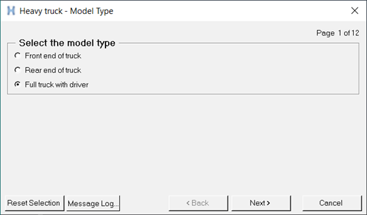
Build a Full Truck Model with Driver
In this step, you will build a full truck model with a driver using the Heavy truck - Model Type dialog.
In MotionView, truck models are assembled from libraries of pre-defined systems using the Heavy Truck library. It guides you through the assembly process, ensuring that your selections are compatible. The Full truck with driver model type builds the model with steering, front suspension, rear suspension, powertrain, and driveline.
- From the Heavy truck - Model Type dialog, select Full truck with driver and click Next.
-
Select the bodies.
- From the Frame drop-down menu, select Ladder-rigid.
- From the Cabin drop-down menu, select Conventional Semi-forward cab.
- From the Cargo drop-down menu, select Container Box.
- From the Instrumentation drop-down menu, select Instrumentation.
- Click Next.
Figure 8. 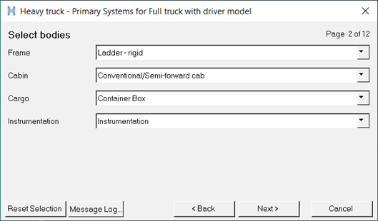
-
Select the primary systems.
- From the Front suspension drop-down menu, select Front solid axle suspension.
- From the Rear suspension drop-down menu, select Rear dual solid axle suspension.
- From the Powertrain drop-down menu, select Linear Torque Map Powertrain.
- Click Next.
Figure 9. 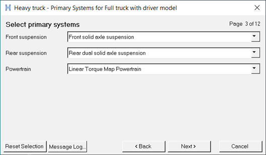
-
Select steering systems.
- From the Steering linkages drop-down menu, select Pitman Arm Steering.
- From the Steering column drop-down menu, select Steering column.
- From the Steering boost drop-down menu, select EPAS.
- Click Next.
Figure 10. 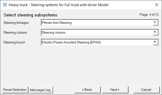
-
Select the springs.
- From the Front spring drop-down menu, select Leaf springs.
- From the Rear spring drop-down menu, select Bell crank linked leaf spring.
- Click Next.
Note: Based on the suspension type selected for the Front suspension and Rear suspension, the Front spring and Rear spring options are modified accordingly.Figure 11. 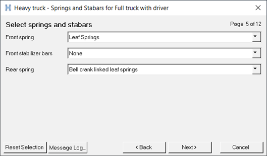
-
Select shock absorbers.
- From the Front shocks drop-down menu, select Front shock absorber (with inline jts).
- From the Rear shocks drop-down menu, select Rear shock absorbers (with inline jts).
- Click Next.
Figure 12. 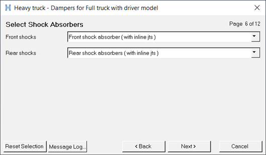
-
Select jounce and rebound bumpers.
- From the Front jounce bumpers drop-down menu, select Front external jounce bumpers.
- From the Front rebound bumpers drop-down menu, select Front internal reb bumpers.
- From the Rear jounce bumpers drop-down menu, select Rear external jounce bumpers.
- From the Rear rebound bumpers drop-down menu, select Rear internal reb bumpers.
- Click Next.
Figure 13. 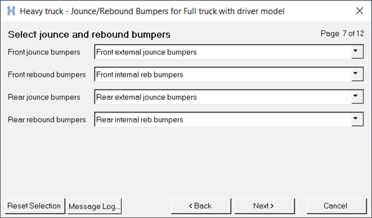
-
Select driveline systems.
Figure 14. 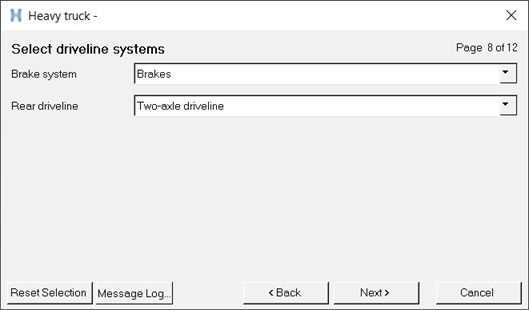
-
Select driveshaft systems.
- From the Rear driveshaft drop-down menu, select Rear Driveshaft 1-piece.
- From the Auxiliary driveshaft drop-down menu, select Secondary driveshaft.
- Click Next.
Figure 15. 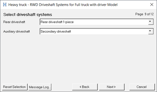
-
Enter a Driver system.
- From the Driver system drop-down menu, select Altair Driver.
- Click Next.
Figure 16. 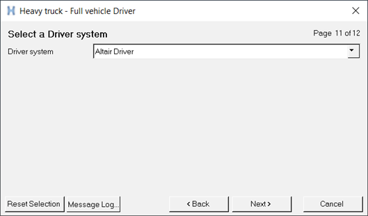
-
Click Finish to complete the process and exit the custom
library wizard.
Figure 17. 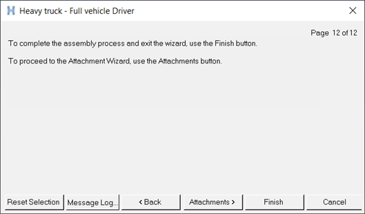
The full truck with driver model is displayed in the modeling window.Figure 18. 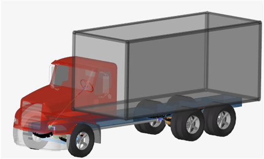
The subsystems that you have selected in the Custom library wizard to build the model are displayed in the Project Browser.Figure 19. 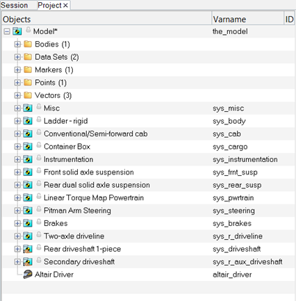
Add Events to the Model
In this step, you will add events to the model you built in Build a Full Truck Model with Driver.
- Altair Driver File
- Brake in Turn
- Constant Radius
- Double Lane Change
- J Turn
- Power off in Straight Line
- Pulse Steer
- Road Course Drive
- Single Lane Change
- Sinusoidal Steering
- Slalom
- Step Steer
- Straight Line Acceleration
- Straight Line Braking
- Swept Sine
- Swept Steer
- Throttle off cornering
- Throttle off Turn in
- N-post shaker
Each event type has different options that needs to be addressed. In the following steps the Constant Radius event is explained.
-
From the Project Browser, right-click on
Model and select Add
Events.
Figure 20. 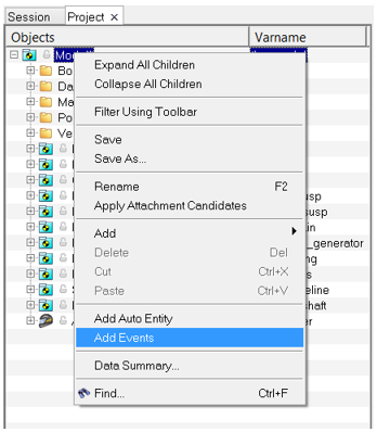
The Add Scripted Driver Task dialog opens. -
From the Type drop-down menu, select the
Constant Radius event and click OK.
Figure 21. 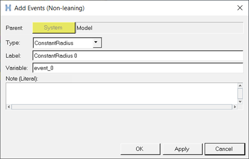
The Constant Radius event is added to the Project Browser.Figure 22. 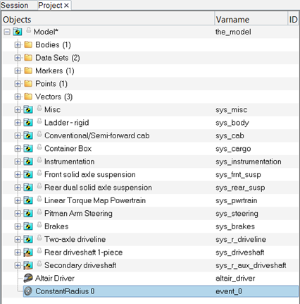
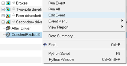
-
Open the Event Editor dialog by right-clicking on the
ConstantRadius 0 event from the Project Browserand select Edit Event from
the context menu.
 The Constant Radius event's parameter is displayed.
 -
Enter the necessary information in the Constant Radius event's parameter.
- Change the Units to meters (m).
- For Radius [m], enter 40.
- For Initial straight [m], enter 20.
- For Initial velocity [m/s], enter 5.
- For Final velocity [m/s], enter 12.
- From the Turn direction drop-down menu, select Left.
- For Transient time [s], enter 10.
- For Look ahead time [s], enter 0.5.
- For Prediction step size, enter 0.01.
- For Print interval [s], enter 0.05.
- From the Output XML File, browse and select the file path.
Figure 23. 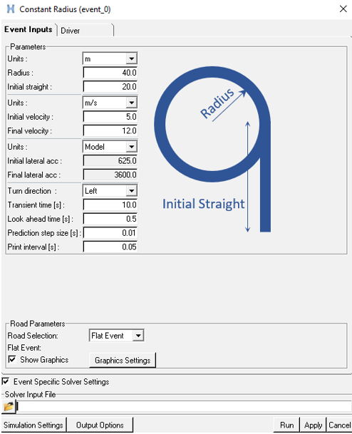
-
Click the Run button.
An ADF (Altair Driver File) is generated with all the event parameters at the XML file path (Output XML File) location. The model is exported and MotionSolve starts to generate the result files. MotionSolve is invoked in the background.
Figure 24. 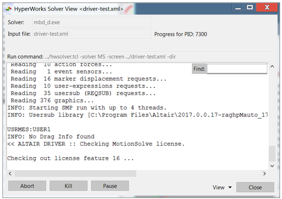
Note: The generated file types include: .adf, .plt, and .h3d files. - Once the MotionSolve run is complete, close the window and return to the MotionView interface.
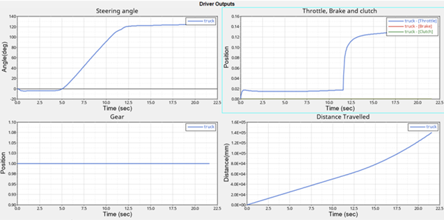
View the Reports
In this step, you will view the reports using the View Reports wizard.
Report templates are a series of pre-defined plots that apply the standard set of plots required for an event. A report template generates all the plots and properly labels them.
-
From the menu bar, click .
Figure 25. 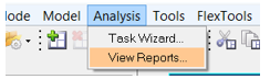
The View Reports wizard is displayed. -
From the View Reports window, select Driver Report and
click OK.
Figure 26. 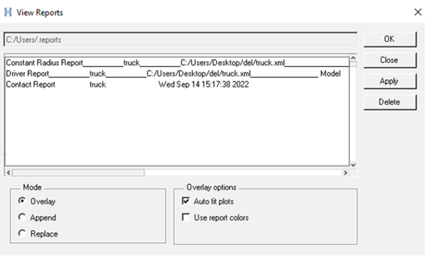
A series of report templates are displayed in the Plot Browser. -
Using the sessions, navigate through the pages and review the results.
Figure 27.