MV-8003: Gear and Clutch Control
In this tutorial, you will learn how to interface gear clutch control for vehicles with manual transmission.
- Gear clutch controller
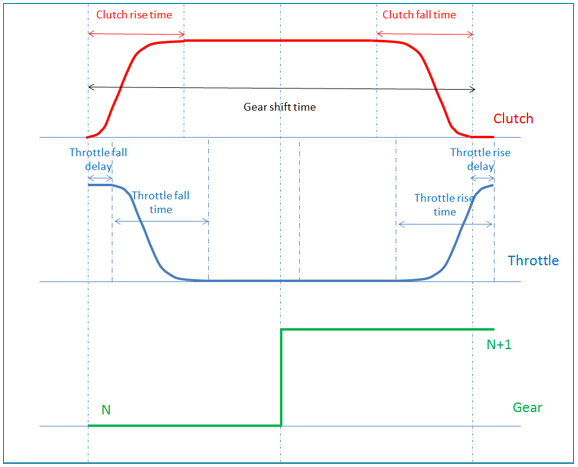
- The Engine speed based shift controller upshifts whenever engine speed goes above the upshift RPM, and it downshifts when the engine speed goes below the downshift RPM. The Gear shift controller also controls the throttle and clutch signal as shown in the figure below.
Assemble the Vehicle
In this step, you will assemble the vehicle using the Assembly Wizard.
- Start a new MotionView session.
-
Ensure the MBD-Vehicle Dynamics Tools preference file loaded is for all of the
MotionView functionality of the Advanced Driver
to work properly.
Figure 2. 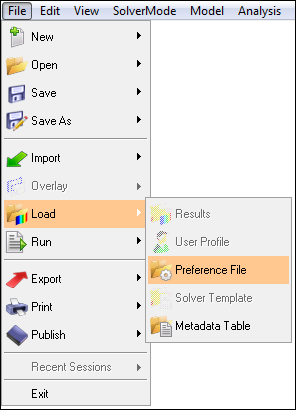
Figure 3. 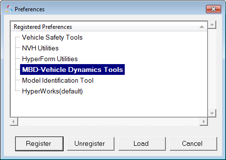
-
From the menu bar, select .
In Script an Open Loop Acceleration Event, a linear torque map powertrain will be used to avoid the complexity of adding controllers for gear and clutch.
Figure 4. 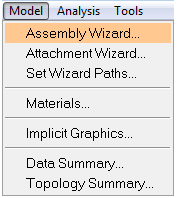
-
Select the Full vehicle with advanced driver
option.
This takes care of all the dependencies of the advanced driver.
Figure 5. 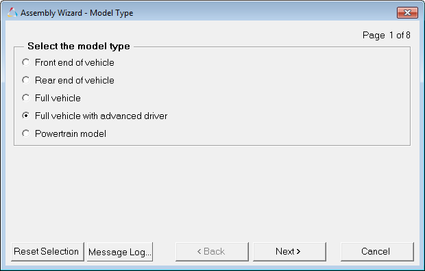
- Click Next.
-
Choose the default selections in the following Assembly Wizard pages.
Page Label Selection Default (Yes/No) 1 Model type Full vehicle with driver No 2 Driveline configuration Front wheel drive Yes 3 Instrumentation Instrumentation Yes 3 Front subframe None Yes 3 Front suspension Frnt macpherson susp (1 pc. LCA) Yes 3 Steering linkages Rackpin steering Yes 3 Rear subframe None Yes 3 Rear suspension Rear quadlink susp Yes 3 Powertrain IC engine friction clutch (manual) No 3 Signal generator Driver signal generator Yes 3 Tires Auto Tires Yes 4 Steering column Steering column 1 (not for Abaqus) Yes 4 Steering boost None Yes 5 Front struts Frnt strut (with inline jts) Yes 5 Front stabilizer bars Frnt stabar with links Yes 5 Rear struts Rear strut (with inline jts) Yes 5 Rear stabilizer bars Rear stabar with links Yes 6 Front jounce bumpers None Yes 6 Front rebound bumpers None Yes 6 Rear jounce bumpers None Yes 6 Rear rebound bumpers None Yes 7 Disk brakes Disk brakes Yes 7 Front driveline Independent fwd Yes 8 Driver System Altair Driver Yes 9 Next No 10 Finish No
Add Driver Analysis
In this step, you will use the Task Wizard to load the driver analysis.
-
From the menu bar, select .
Figure 6. 
-
Select AltairDriverFile from the Type drop-down
menu.
Figure 7. 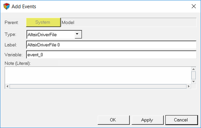
Tip:Selecting
 (Altair Driver
icon) will open up the Altair Driver panel.
This automatically resolves all of the vehicle attachments for the
Altair Driver.
(Altair Driver
icon) will open up the Altair Driver panel.
This automatically resolves all of the vehicle attachments for the
Altair Driver.Figure 8. 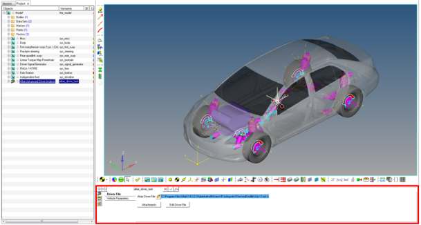
Selecting the AltairDriverFile 0 will open up the driver event panel. Selecting the Event Editor button will open the Altair Driver File dialog.
Specify Vehicle Parameters
In this step, you will specify parameters for the vehicle.
Write an Altair Driver File Driving Event
In this step, you will create a constant radius with constant velocity event, a straight line acceleration event, and a path as a table of cartesian coordinates of centerline points event.
Velocity Profile Following with Gear and Clutch Controller
In this step, you will modify the ADF written in Path as a Table of Cartesian Coordinates of Centerline Points Event of MV-8001: Path and Velocity Following and incorporate a gear and clutch controller.
-
Open any text editor and copy and paste the following text into it.
Important: All blank lines must be removed prior to saving the file.Tip: Read through the comments for a better understanding on what is written in the ADF.
$-----------------------------------------------------------------ALTAIR_HEADER [ALTAIR_HEADER] FILE_TYPE = 'ADF' FILE_VERSION = 1.0 FILE_FORMAT = 'ASCII' $--------------------------------------------------------------------------UNITS [UNITS] (BASE) {length force angle mass time} 'meter' 'newton' 'radians' 'kg' 'sec' $--------------------------------------------------------------------VEHICLE_IC [VEHICLE_INITIAL_CONDITIONS] VX0 = -20.0 VY0 = 0.0 VZ0 = 0.0 $--------------------------------------------------------------STEERING_STANDARD [STEER_STANDARD] MAX_VALUE = 3.141593 MIN_VALUE = -3.141593 SMOOTHING_FREQUENCY = 10.0 INITIAL_VALUE = 0.0 $--------------------------------------------------------------THROTTLE_STANDARD [THROTTLE_STANDARD] MAX_VALUE = 1.0 MIN_VALUE = 0.00 SMOOTHING_FREQUENCY = 10.0 INITIAL_VALUE = 0.2 $---------------------------------------------------------------BRAKING_STANDARD [BRAKE_STANDARD] MAX_VALUE = 1.0 MIN_VALUE = 0.0 SMOOTHING_FREQUENCY = 10.0 INITIAL_VALUE = 0.0 $---------------------------------------------------------------GEAR_STANDARD [GEAR_STANDARD] MAX_VALUE = 6 MIN_VALUE = 1 INITIAL_VALUE = 1 $---------------------------------------------------------------CLUTCH_STANDARD [CLUTCH_STANDARD] MAX_VALUE = 1 MIN_VALUE = 0 SCALING_FACTOR = 1 INITIAL_VALUE = 0.0 $-----------------------------------------------------------------MANEUVERS_LIST [MANEUVERS_LIST] { name simulation_time h_max print_interval} 'MANEUVER_1' 10.0 0.01 0.01 $---------------------------------------------------------------------MANEUVER_1 [MANEUVER_1] TASK = 'STANDARD' (CONTROLLERS) {DRIVER_SIGNAL PRIMARY_CONTROLLER ADDITIONAL_CONTROLLER} STEER FEEDFORWARD_STEER NONE THROTTLE FEEDFORWARD_TRACTION NONE BRAKE FEEDFORWARD_TRACTION NONE GEAR GEAR_CLUTCH_CONTROL NONE CLUTCH GEAR_CLUTCH_CONTROL NONE $---------------------------------------------------------STEER [FEEDFORWARD_STEER] TAG = 'FEEDFORWARD' LOOK_AHEAD_TIME = 0.5 $Instruction to the driver that the path is of type DDF PATH = 'DDF' $Path of the ddf file, data lies in same folder in file named snet.ddf FILE = 'snet.ddf' $--------------------------------------------------THROTTLE & BRAKE [FEEDFORWARD_TRACTION] TAG = 'FEEDFORWARD' TYPE = 'FOLLOW_VELOCITY' LOOK_AHEAD_TIME = 0.5 DEMAND_SIGNAL = 'DEMAND_SPEED' $---------------------------------------------------------DEMAND_SPEED $Block containing all the information about the acceleration profile to be followed [DEMAND_SPEED] TYPE = 'CURVE' $Velocity profile information is in the file snet.ddf in the same folder $Velocity profile is defined under the column name DV in the DDF ${X Y Z DV} FILE = 'snet.ddf' DEMAND_VECTOR = 'DV' $Gear clutch controller [GEAR_CLUTCH_CONTROL] TAG = 'ENGINE_SPEED' (GEAR_SHIFT_MAP) {G US DS CT CRT TFD TFT CFT TRD TRT} 1 650 285 0.45 0.05 0.1 0.1 0.05 0.05 0.05 2 650 285 0.45 0.05 0.1 0.1 0.05 0.05 0.05 3 650 285 0.45 0.05 0.1 0.1 0.05 0.05 0.05 4 650 285 0.45 0.05 0.1 0.1 0.05 0.05 0.05 5 650 285 0.45 0.05 0.1 0.1 0.05 0.05 0.05 -
Click
 to run the
simulation.
- Observe the results.
