MV-8800: Add the Altair Driver to a Non-wizard Two-wheeler Model and Simulate a Slalom Event
In this tutorial, you will learn how to add the Altair Driver in any model built outside the Assembly Wizard Library and run the full vehicle events available in MotionView.
- What is Altair Driver?
- The Altair Driver is a system consisting of a control library and signal
control managers needed to perform full vehicle events simulations in
MotionView. Using the Altair Driver any number of full vehicle events
can be simulated including:
- Scripting simulations: break up the simulation into different maneuvers
- Open-loop, closed-loop, and user-defined controllers
- Following path and speed profiles
Assembling vehicles using the MotionView Assembly Wizard allows the selection of the Altair Driver while building the model. However, when the vehicle is modeled outside the wizard library, the Altair Driver has to be added manually if it is desired to simulate full vehicle events.
In this tutorial, the Altair Driver will be added in a non-wizard motorcycle model created using MotionView entities from an imported CAD model. To add the Altair Driver, a Powertrain and Brake systems will be created and linked with the Altair Driver. Once the Altair Driver is set in the model, a Slalom event will be included to perform the simulation.
- Non-wizard Motorcycle Model
- The motorcycle model available for this tutorial is a basic multibody
model consisting of points, bodies, graphics, joints, spring dampers,
and AutoTires (see Auto Tire - Auto Entity for
additional information). No direct template or control-based systems are
available inside the model to control the speed and lateral dynamics.
The front and rear suspensions were tuned for stiffness, damping, and
preload properties. The model,
Motorcycle_Tutorial.mdl, reads the graphics
information from the H3D file
Motorcycle_Tutorial_graphic.h3d.
Figure 1. Tutorial motorcycle model 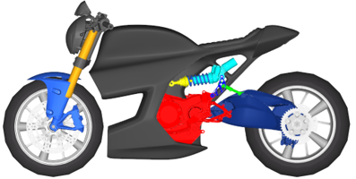
The steps below will guide you in creating a simple “Linear torque map” powertrain and brake torque systems to help in controlling the vehicle speed during event simulations.
Before you begin, copy the files Motorcycle_Tutorial.mdl and Motorcycle_Tutorial_graphic.h3d, located in the mbd_modeling\driver_motorcycle folder, to your <working directory>.
Create the Powertrain System
-
In a MotionView session, on the menu bar, click to open the Preferences dialog.
- Select MBD-Vehicle Dynamics Tools.
- Click Load.
Figure 2. 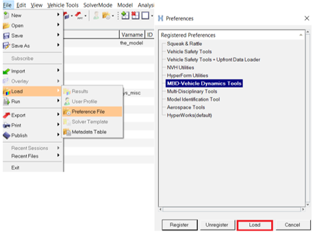
-
On the menu bar, click and select Motorcycle_Tutorial.mdl to open
the non-wizard motorcycle model.
Figure 3. Motorcycle_Tutorial.mdl opened in MotionView 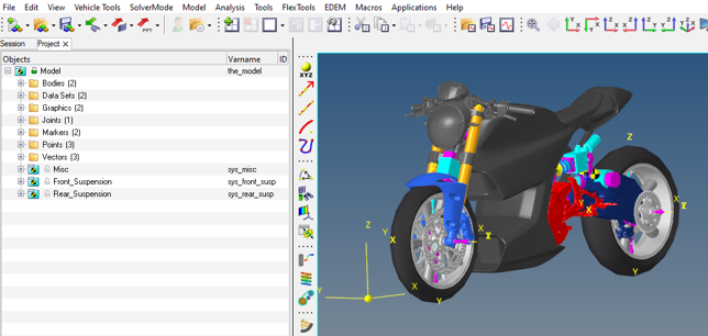
-
Right-click on to create a Powertrain system.
Figure 4. 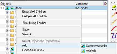
-
Enter sys_powertrain as the Variable name, and
Powertrain as the Label.
Figure 5. 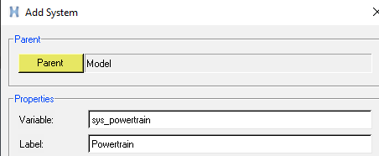
-
Add a Dataset in the Powertrain system by right-clicking on . Enter Powertrain Data as the name.
Figure 6. 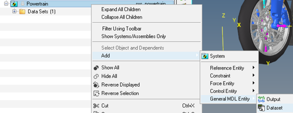
-
In the created Dataset, under Data Members, create three
data members of Type Real named:
- Throttle scaling
- Max torque
- Min torque
Figure 7. 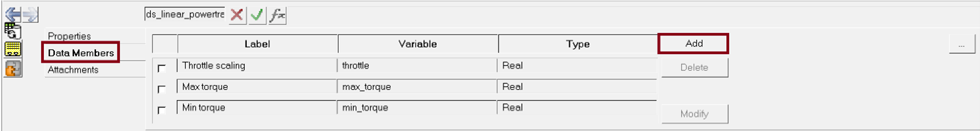
-
Under Properties, enter values for data members:
- Throttle scaling = 1
- Max torque = 150000
- Min torque = -500
Figure 8. 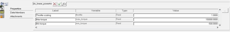
-
Right-click on to create a solver array and label it as
Powertrain.
Figure 9. 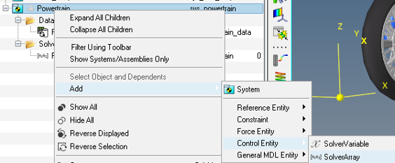
-
In the created Powertrain solver array, under Values,
select the Edit check box and Append
5 Data point values.
Figure 10. 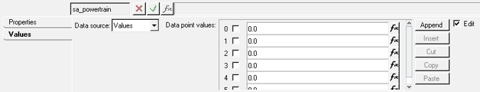
-
Using the fx button, select the Max
Torque dataset value and add it to the expression in the Data
point value 1.
Figure 11. 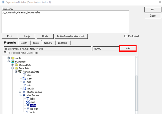
Or enterds_powertrain_data.max_torque.valuein the array Data point value 1.Figure 12. 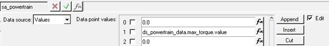
-
Repeat the previous step adding the
Min torqueandThrottle Scalingvalues dataset in the arrays in the Data point values 2 and 3.Figure 13. 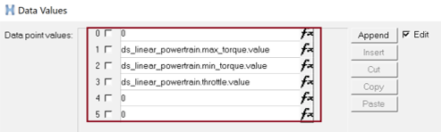
Note: The zero value signals in the solver array are needed to maintain consistency with the IC Engine Friction Clutch Powertrain. -
Right-click on to create 5 solver variables as follows:
Label Variable Throttle sv_throttle Gear sv_gear Clutch sv_clutch Powertrain Speed sv_powertrain_speed Brake sv_brake Drive Torque sv_drive_torque Figure 14. 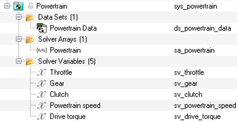
-
In the Powertrain speed solver variable, modify the type to
Expression under Properties
and enter the expression:
`-WY({MODEL.sys_rear_susp.b_Rear_Wheel.cm.idstring},{MODEL.sys_rear_susp.b_SwingArm.cm.idstring})`Figure 15. 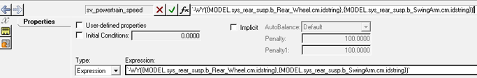
Note: This expression measures the angular speed of the rear wheels referred to the swing arm. The Altair Driver predicts the vehicle speed using the wheel angular speed and sets the required throttle to achieve the speed demand. If any gear ratio exists between wheel and powertrain, it needs to be multiplied with the wheel angular speed inside Powertrain solver variable expression. -
In the Drive torque solver variable, select the
User-defined properties option.
Figure 16. 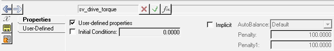
-
15. Under the User-defined tab, enter in the User
expr:
`USER(1,{sa_powertrain.idstring},{sv_throttle.idstring})` -
Select the Use local file and function name check box,
enter
msautoutilsunder Local File and VIRTUAL_POWERTRAIN under Function name.Figure 17. 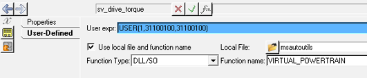
The solver signal specified by the user expression in the solver variable computes the Drive torque for the given throttle input from the Altair Driver. The drive torque solver variable reads the information from the Powertrain solver array data source 1 and the Driver throttle solver variable. For more information about the linear torque map powertrain see Linear Torque Map Powertrain.
-
Right-click on to create a force entity to apply the drive torque in the rear
wheel. Label the force .
Figure 18. 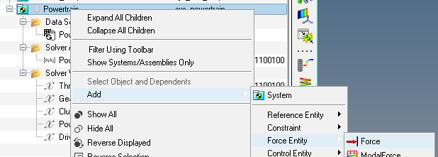
-
Under Connectivity, change the Force type to
Action reaction and Properties to
Rotational. Select Rear_Wheel
as Body 1, SwingArm as Body 2, and
Wheel_Center as Point 1.
Figure 19. 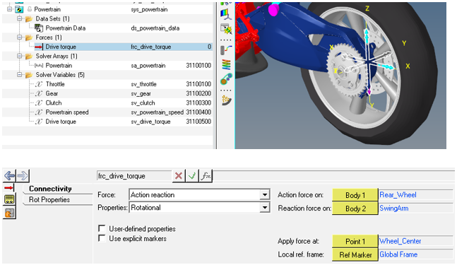
Note: If the entities selection is not available, clear the option Only show entities within valid scope.Figure 20. 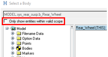
-
In the Drive torque force entity, under Rot Properties,
change Ty to expression and enter:
`-VARVAL({sv_drive_torque.idstring})`Figure 21. 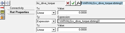
- Right-click on to add a curve entity under the Powertrain system named Gear Ratio.
-
Change the x and y type to values and enter
(0,0) and (1,1) as shown
below.
Figure 22. 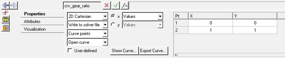
This curve is required to maintain consistency with the IC Engine Friction Clutch Powertrain that models a manual transmission. The linear torque map engine used in this tutorial has only one gear ratio.Note: The Clutch and Gear solver variables are unused signals present to maintain consistency with the IC Engine Friction Clutch Powertrain and they are also needed to resolve the driver attachment.
Create the Brake System
-
Right-click on to create the Brake system.
Figure 23. 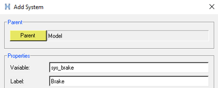
-
Right-click on to create the brake solver variable, Label it
Brake.
Figure 24. 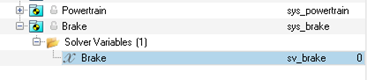
-
Right-click on to create 2 force entities to apply the
brake torque in the front and rear wheel. Label them Front Brake
Torque and Rear Brake Torque.
Figure 25. 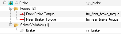
-
Click on Front Brake Torque. Under
Connectivity, change the Force to Action
Reaction, and Properties to Single Component
Rotational. Select the Front_Wheel for
Body 1, ShockRod for Body 2,
Wheel_Center of the front wheel for Point 1, change
the Direction to Vector and select Global
Y.
Figure 26. 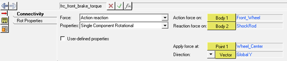
-
Under Rot Properties, change T: to
expression and enter:
`VARVAL({sv_brake.idstring})*10000`. -
Click on Rear Brake Torque. Under
Connectivity, change the Force to Action
Reaction, and Properties to Single Component
Rotational. Select the Rear_Wheel for
Body 1, SwingArm for Body 2,
Wheel_Center of the rear wheel for Point 1, change
the Direction to Vector and select Global
Y.
Figure 27. 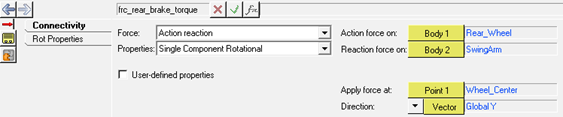
-
Under Rot Properties, change T: to
Expression and enter:
`VARVAL({sv_brake.idstring})*10000`.Figure 28. 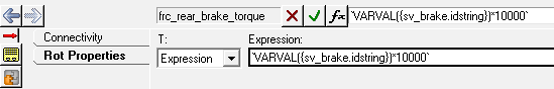
Add the Altair Driver in the Model
-
Right-click on . Select Altair Driver and click
OK.
Figure 29. 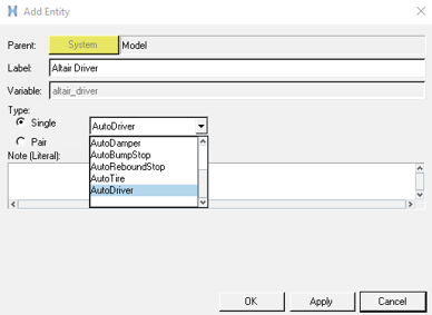
Note: An Info dialog is shown asking to set the vehicle configuration on the Altair Driver panel. The vehicle configuration has the Front and Left vectors defined according to the orientation of the vehicle and is used as reference for the Altair Driver to control the vehicle. In case the vehicle model is created in a different coordinate system than Front: -X and Left: -Y, the Vehicle Orientation in the Altair Driver panel must be changed to the model’s reference.In cases where the vehicle has more than two wheels, but the vehicle body is expected to lean, the Vehicle Configuration can be modified to “Leaning” or “Non-leaning”. According to this selection, leaning or non-leaning events can be added in the model.Figure 30. 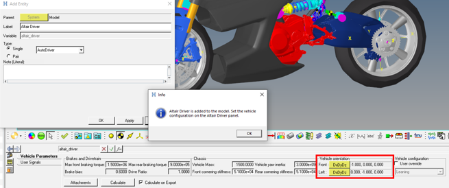
-
In the Altair Driver panel, click on Attachments.
Populate the attachment as follows:
Vehicle Attachments Selection Vehicle Body (Body) Vehicle_Body Required for the Altair Driver to calculate the velocities, accelerations, and position of the vehicle. Engine Speed (Solver Variable) Powertrain speed Required to estimate the engine speed. Path Reference (Marker) Road_Reference Required to predict the path and to recognize the road surface, its origin and orientation. Gear Ratios (Curve) Gear Ratio Required gear ratios to multiply the drive torque. In this tutorial a dummy curve was created and is not used in the powertrain. Driver Outputs Selection Steering Joint (Joint) Steering Required joint for applying the steering control torque/motion from the Altair Driver in the model. Brake output (Solver Variable) Brake Receives the brake values from the Altair Driver to be applied in the Brake torque entity. Clutch output (Solver Variable) Clutch Receives the clutch configuration On/Off from the drive. For the linear powertrain, present in this tutorial, this is not used. Throttle output (Solver Variable) Throttle Receives the throttle output from the Altair Driver to be applied in the powertrain model based on the demand torque/vehicle speed. Gear output (Solver Variable) Gear Receives the gear position from the Altair Driver. Vehicle Constraints (optional) Selection Constraint – 1 (Joint) Planar_joint_for_statics Constrain the vehicle from yawing while solving the static simulation. After the static, this joint is deactivated. Drive Joint (Joint) Wheel_Rear Used to lock the rear wheel while solving the static simulation. After the static, this joint is deactivated. Note: These attachments are optional and can be left unresolved, however, to achieve a good static solution and equilibrium position, it is recommended that all attachments are resolved.Figure 31. 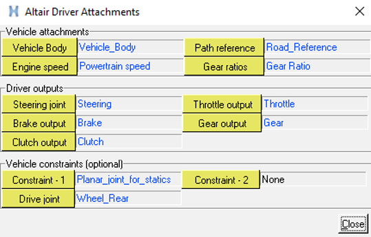
Add the Slalom Event and Simulate the Model
-
Right-click on Model in the browser and select
Add Events from the context menu.
Figure 32. 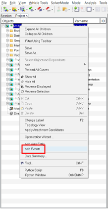
-
Select Slalom from the events list and click
OK.
Figure 33. 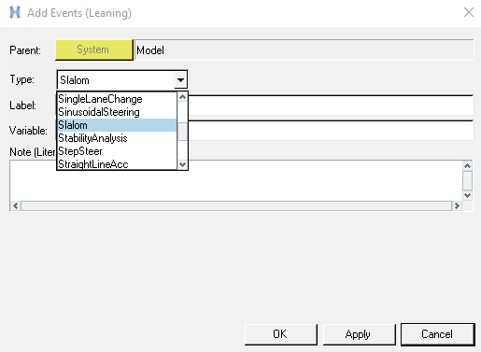
-
Right-click on the Slalmom event and select
Edit Event.
Figure 34. 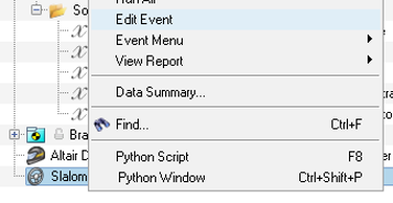
-
In the Slalom event, change the number of cones to 10,
modify the velocity units to km/h, and set
45km/h as the velocity.
Figure 35. 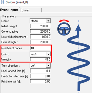
Under the Driver tab it is possible to select the steering control input between Motion and Torque, and modify the PID control gains.Figure 36. 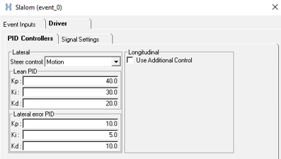
-
Under Solver Input File, browse to the location to save the run model defining
the file name, and click on Run to simulate the Slalom
Event.
Figure 37. 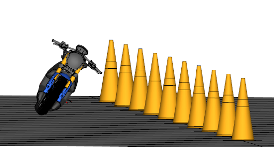
Add External Controls in the Altair Driver (Optional)
- Open Loop User Defined Signals
In this step the vehicle lean control is set from User Signals to replace the ADF Driver commands defined by a Step Steer Event.
-
Under the Altair Driver in the User
Signals tab, select Signal 0, modify the
Type to Expression, and enter:
`Step(time,5,0,10,10D)`.Figure 39. 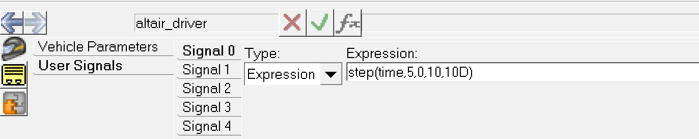
- Right-click on . Select StepSteer, Label = StepSteer and Variable = event_stepsteer, and click OK.
-
Right-click on the StepSteer event, under
Event Menu select Build
Event.
Figure 40. 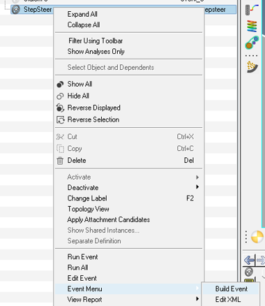
The Build Event will generate the necessary files to simulate the model.Note: If not specified the Solver Input File folder using the Event Editor, a folder named Events will be created in the same location where the model .mdl is saved. The Build Event option will store the files in that folder. -
Open the file event_stepsteer.adf in a text editor,
modify the DEMAND_LEAN block to include the MotionView signal.
Figure 41. 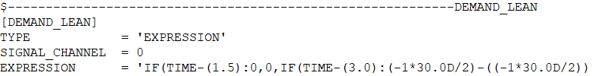
-
Under Type enter
‘MOTIONVIEW’, keep the Signal_Channel 0 as also specified in the MotionView model, and remove or comment out the expression line.Figure 42. 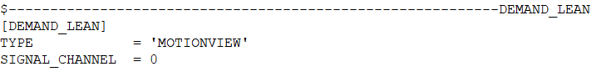
-
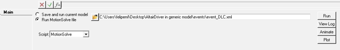
Save the event_stepsteer.adf file. From the MotionView Run panel, select Run MotionSolve
file, locate the exported
event_stepsteer.xml, and click
Run.
Figure 43. 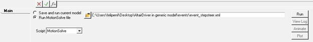
- Closed Loop User Defined Signals
In this step the traction control inputs defined in a Double Lane Change event will be replaced with a Step function expression.
-
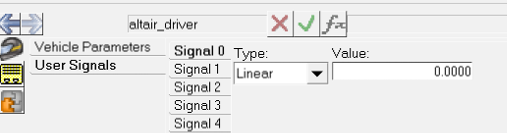
Under the Altair Driver in the User
Signals tab, select Signal 1, modify the
Type to Expression and enter:
`Step(time,1,10000,5,20000)`.Figure 44. 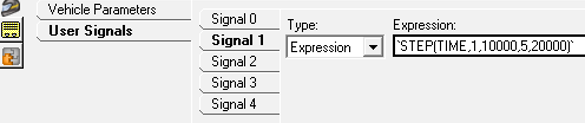
- Right-click on . Select Double Lane Change, Label = DoubleLaneChange, and Variable = event_DLC, and click on OK.
-
Right-click on the DoubleLaneChange event, under
Event Menu select Build
Event.
Figure 45. 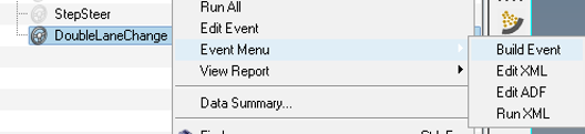
The Build Event will generate the necessary files to simulate the model.Note: If not specified the Solver Input File folder using the Event Editor, a folder named Events will be created in the same location where the model .mdl is saved. The Build Event option will store the files in that folder. -
Open the file event_DLC.adf in a text editor, modify the
DEMAND_SPEED block to include the MotionView
signal.
Figure 46. 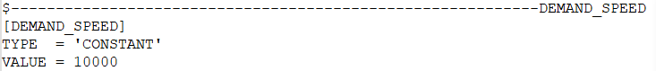
-
Under Type enter
‘MOTIONVIEW’, replace the line VALUE = 1000 withSIGNAL_CHANNEL = 1.Figure 47. 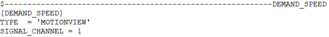
-
Save the event_DLC.adf file, in the MotionView Run panel, select Run MotionSolve
file, locate the exported event_DLC.xml,
and click Run.
Figure 48.