MV-8600: Road Reference Marker
In this tutorial you will learn how to modify the road property file and road reference marker to position a plank road in a single tire model.
- Introduction
-
Road reference marker is the coordinate system that is used by MotionSolve to evaluate the position and orientation of the road. The road file will be evaluated with respect to the road reference marker which is also included in the Auto Tire system attachment.
Figure 1. 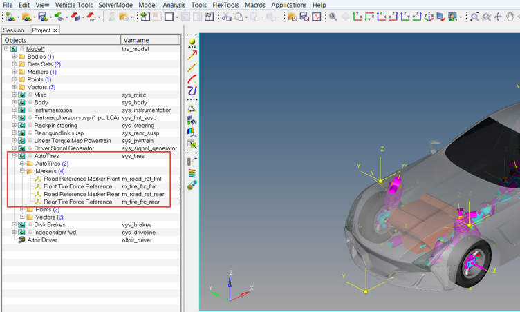
- Road Reference Marker - TNO Plank Road Model
-
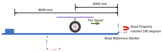
The TNO Plank Road is represented by flat road with a single cleat (cuboid obstacle) that can be oriented in perpendicular or oblique direction related to the X-axis of the Road Reference Marker.
Figure 2. Plank Road Oriented by the Road Reference Marker 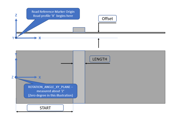
The Offset is the distance of the ground with respect to the Z-axis of the Road Reference Marker. Length measures the width of the plank along X-axis. Rotation angle XY plane is the positive X-axis of the road with respect to the inertial frame. START parameter indicates the distance along the X-axis of the road from the origin to the start of the plank.
In this tutorial you will learn how to modify the road property file and road reference marker to position the plank road in a single tire model. By plotting the tire forces vs tire patch location, you will understand the influence of the marker and road property in the simulation results.
- Files Required
- The following files listed in the table are required for the tutorial. Copy
the given files, located in the
mbd_modeling\road_marker folder, to your
<working directory>.
Files File Type RoadRefMarker.mdl MDL File TNO_PlankRoad.rdf Road Property File
Start MotionView and Analyze the Model
- From the Start menu, select .
-
Click and load the RoadRefMarker.mdl file.
Figure 3. 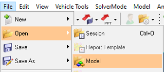
Figure 4. 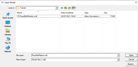
-
Click Open
The model is displayed in MotionView.
Figure 5. 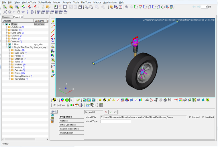
Note that the Road Reference marker is located at the contact patch of the tire.Figure 6. 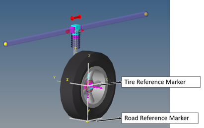
-
The Auto Tire sub-system has the TNO_PlankRoad.rdf file as
the Road property file.
Figure 7. 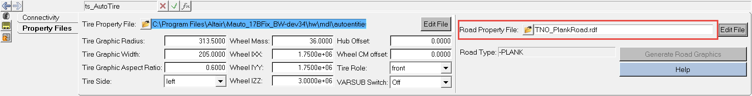
-
The image below shows the parameters available in the road property file.
Figure 8. 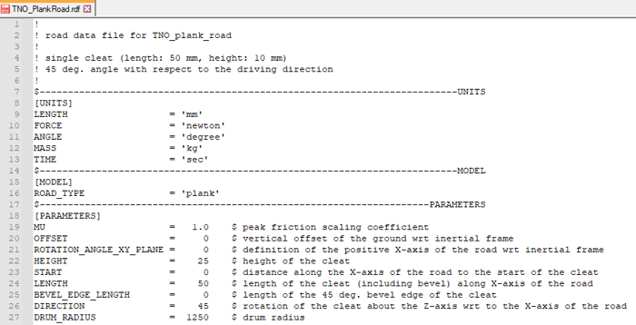
Parameters Description HEIGHT Height of the cleat. START Distance along the X-axis of the road from the origin to the start of the cleat (in other words, travelling from the origin the tire will hit the cleat at START). LENGTH Length of the cleat (including bevel) along the X-axis of the road. BEVEL_EDGE_LENGTH Length of the 45 deg. Bevel edge of the cleat. DIRECTION Rotation of the cleat about the Z-axis with respect to the Y-axis of the road. If the cleat is placed crosswise, DIRECTION = 0. If the cleat is along the X-axis, DIRECTION = 90. Note: Refer to TNO MF-SWIFT/MF-Tyre Documentation for additional information.
Change the START Parameter in the Road File and Verify the Results
-
Change the START parameter to 4000 in the
TNO_PlankRoad.rdf file.
Figure 9. 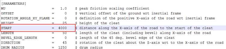
-
On the Model-Main toolbar, click the Run
 icon to open the Run Solver panel.
-
Browse and locate the required file path to save and run the current
model.
Figure 10. 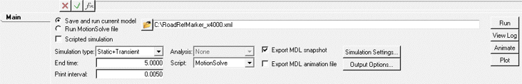
-
Click the Run button (located on the far right side of
the panel).
MotionSolve is invoked in the background and runs the simulation.
-
After the MotionSolve run is complete, click on
Results.
A new window with HyperView will open and the animation of the model can be visualized.
Figure 11. 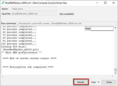
-
Open a HyperGraph 2D session from Client selection
menu (as shown below).
Figure 12. 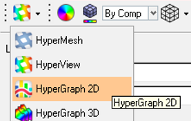
-
Use the Data file browser to locate the
.plt file saved in the MotionSolve simulation.
Figure 13. 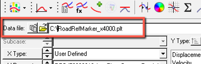
-
Define the X-axis by selecting the following options as shown below.
Figure 14. 
X Type User Defined X Request REQ/70000018 AutoTire- Contact Patch Locations X Component f2 -
Define the Y-axis by selecting the following options.
Figure 15. 
Y Type User Defined Y Request REQ/70000014 AutoTire- Tire CP Forces (W-Axis system) Y Component f4 -
Click the Apply button to obtain the following
plots.
Figure 16. 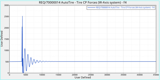
The plot displays the Tire force (Y-axis) vs Contact patch location. The curve indicates the oscillation starting at 4000mm along the X-axis, meaning the tire reaches the obstacle at 4000mm.
Change the START Parameter to 8000 in the Road File and Verify the Results
-
Change the START parameter to 8000 in the
TNO_PlankRoad.rdf file.
Figure 17. 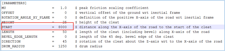
-
On the Model-Main toolbar in MotionView, click the (Run) icon to open the Run Solver panel.
-
Browse and locate the required file path to save and run the current
model.
Figure 18. 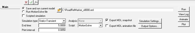
-
In the same HyperGraph session, browse and locate the new
.plt file in the Data file field.
Figure 19. 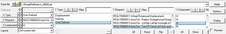
-
Repeat the X and Y-axis selections.
Figure 20. 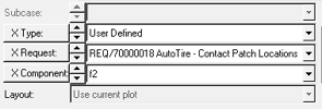
X Type User Defined X Request REQ/70000018 AutoTire- Contact Patch Locations X Component f2 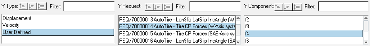
Y Type User Defined Y Request REQ/70000014 AutoTire- Tire CP Forces (W-Axis system) Y Component f4 -
Click the Apply button to visualize the two plots
overlayed.
Figure 21. 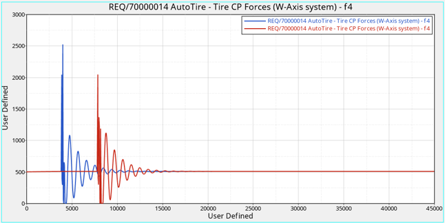
The plot shows the modifications on Start parameter in the Road Property File. The blue curve indicates the obstacle at 4000mm along the X-axis, while the red curve shows the obstacle at 8000mm.
Change the Road Reference Marker Position and Verify the Results
-
In the MotionView model, click on the Marker Road
Reference in the browser.
Figure 22. 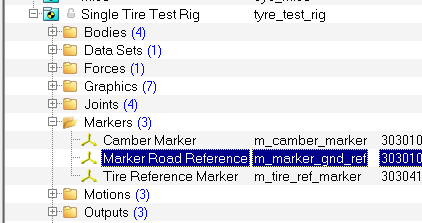
-
The Road Reference Marker's origin uses the Ground reference point.
Figure 23. 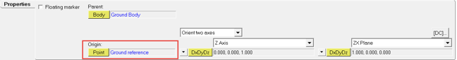
-
Click on the Ground reference point from the Project Browser.
Figure 24. 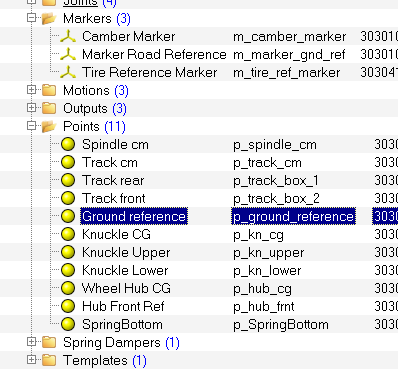
-
In the panel area, change the X coordinate value to
4000.
Figure 25. 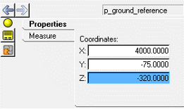
-
On the General Actions toolbar, click the (Run) icon to open the Run Solver panel.
-
Click the Run button and run the simulation indicating a
different name for the results file.
Figure 26. 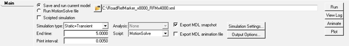
-
In the HyperGraph session, browse and locate the respective plot file from the
<working directory> in the Data
file field.
Figure 27. 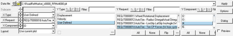
-
Repeate the X and Y-axis selections.
Figure 28. 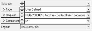
X Type User Defined X Request REQ/70000018 AutoTire- Contact Patch Locations X Component f2 Figure 29. 
Y Type User Defined Y Request REQ/70000014 AutoTire- Tire CP Forces (W-Axis system) Y Component f4 -
Click the Apply button to visualize the three plots
overlayed.
Figure 30. 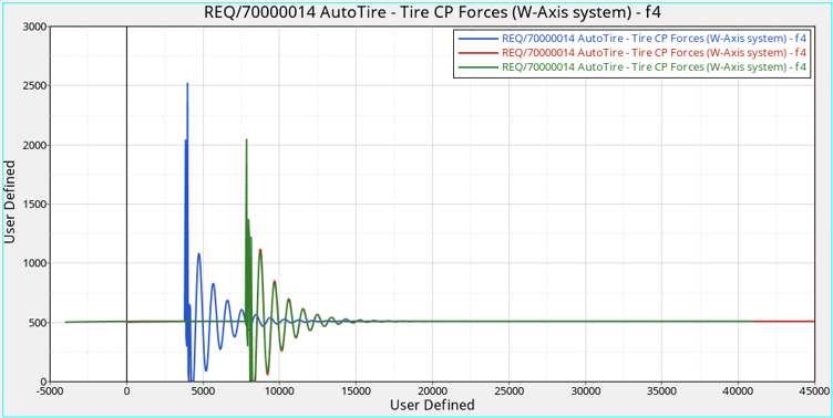
The green curve shows the results of modifying the Road Reference Marker 4000mm keeping the start at 8000mm. You may notice that plot indicates the obstacles at 8000mm as in Step 3, but the starting point is not 0mm as before but -4000mm in X. The explanation for this is shown in the image below. The Road Reference Marker works as the reference for the road, since the marker was moved, the contact patch is now behind the reference, hence starting at a negative value.Figure 31. 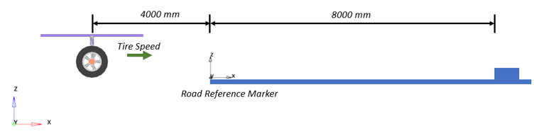
Change the Rotation Angle XY Plane to 180 and Verify the Results
-
Change the ROTATION_ANGLE_XY_PLANE parameter to 180 in the
TNO_PlankRoad.rdf file.
Figure 32. 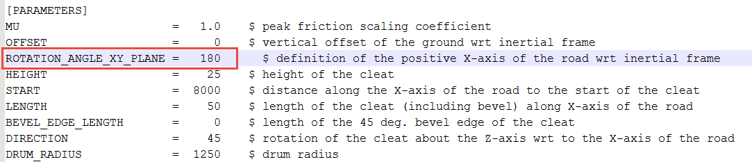
-
Click the Run button and run the simulation indicating a
different name for the results.
Figure 33. 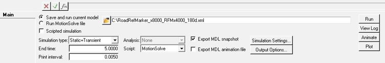
-
In the HyperGraph session, browse and locate the respective plot file from the
<working directory> in the Data
file field.
Figure 34. 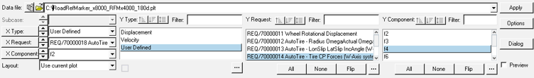
-
Repeat the X and Y-axis selections.
Figure 35.
X Type User Defined X Request REQ/70000018 AutoTire- Contact Patch Locations X Component f2
Y Type User Defined Y Request REQ/70000014 AutoTire- Tire CP Forces (W-Axis system) Y Component f4 -
Click the Apply button to visualize the four plot
overlayed.
Figure 36. 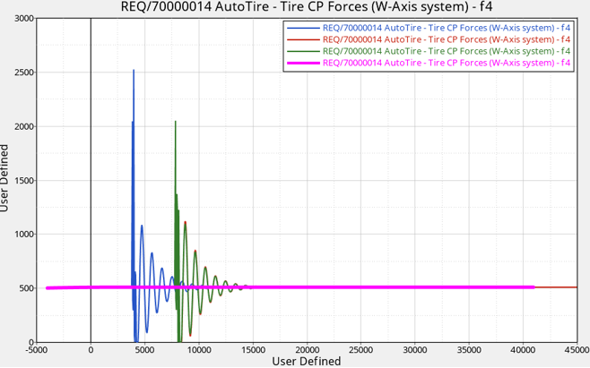
The pink curve shows the results of rotating the Road Property File 180 degrees. It can be observed that there are no oscillations and the tire does not reach the obstacle. The explanation for this is shown in the image below. When rotating the road, the cleat moves behind the tire and opposite to the tire direction.Figure 37.