Geometry Repair for External Aerodynamics Simulation using the Template Manager
In this tutorial we are going to prepare the geometry of a car for an external aerodynamics simulation. First, some tasks will be executed manually. Then a Template will be created and run to automate most of the pre-processing procedure.
Overview
HyperMesh CFD’s Aerodynamics and Aeroacoustics solutions utilize Altair’s ultraFluidX, an Immersed Boundary, Lattice Boltzmann solver, which allows for increased flexibility in its input geometry as compared to other solvers. Definitions, requirements, recommendations, and considerations related to this input geometry are specified below.
Definitions
- Wetted surface/element
- The portion of the input geometry which will be in direct contact with the flow being simulated.
- Solid region
- The region of the domain where the flow shall not be evaluated.
- Class-A surfaces or flow-critical surfaces
- Surfaces which are exposed to high-speed flow, large pressure/velocity gradients and/or surround flow-critical gaps.
- Baffle surface
- A zero-thickness surface which is immersed in the flow and does not form any enclosed region (it is not part of a solid region).
Requirements
- All elements in the input mesh must be triangles.Note: 1st order triangles are preferred as the solver will ignore any additional information provided by 2nd order triangles.
- The normal vector of all wetted elements must point towards the side of the
element which will be in direct contact with the flow.Note: The simulation will likely run even if the normal vectors are incorrectly assigned. However, unexpected changes to the geometry and/or errors in force measurements would be likely in this case.
- Solid regions may be defined by elements which are not connected, even when gaps exist between these. However, these gaps must be smaller than ½ the size of the voxel (a cubic fluid element) which will intersect the element. Larger gaps may cause the solver to treat the intended solid region as a fluid region.
- Baffle surfaces must be identified as such and in their own separate
parts.Note: Usually, we prefer to thicken baffle surfaces to create a solid region.
Recommendations
- Model all heat exchanger cores as Porous Media, which is represented in the
input mesh as a rectangular volume with separate inlet, outlet, and wall
surfaces.Note: Detailed heat exchanger cores will be accepted by the solver. However, properly calculating the pressure drop across these would vastly increase resource requirements while providing little to no benefit when compared to the alternative.
- Mesh all Class-A surfaces with < 0.1 mm deviation for CAD input.
- Limit maximum element size to 50 mm on full-scale vehicles (scale for scaled
vehicles).Note: ultraFluidX will write results directly on the surface elements as defined in the model. If these elements are larger than the surrounding voxels, some results definition will be lost upon writing. ultraFluidX provides an option to automatically split large elements which eliminates the need to limit the element size within the geometry model. This option is addressed in the setup tutorial.
- Wrap (but do not simplify) components whenever a solid region is desired but
gaps or openings exist which would require more than just trivial manual
work to close. Use HyperMesh CFD’s Auto tool when possible to retain
geometry details. Do not use any other Enclosure tool except Auto on Class A
surfaces.Note: In CFD modeling, input parts can have topology issues, like free surfaces and self-intersections, and part assembly issues, such as parts with very close proximity and intersecting parts. Manually connecting these parts can be time consuming and require expertise in certain tools. The Enclosure tool can generate a watertight manifold model from dirty input with considerably less manual work.
Considerations
ultraFluidX was built to accept complex geometries without issue. Unless a portion of the geometry is being replaced by a model (for example, ), there is no need to simplify the geometry.
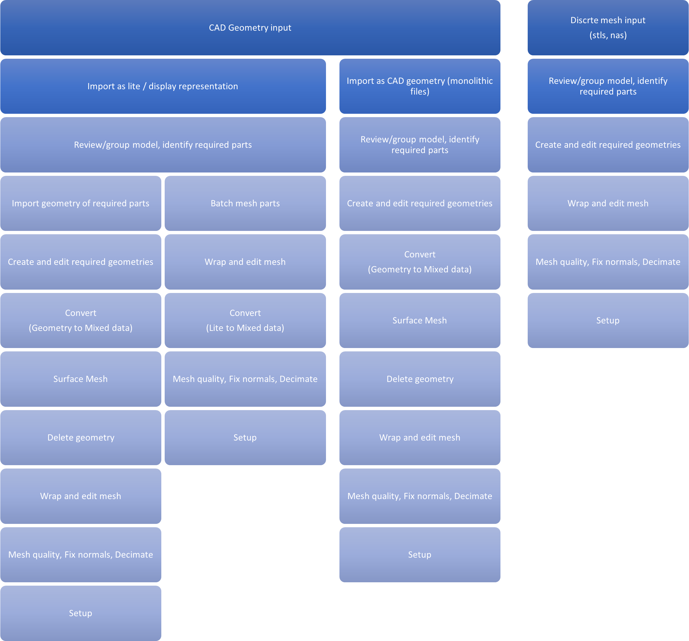
Generic Process Diagram
Start Session, Set Solution and Modelling Environment
Create a New Session
-
Launch HyperMesh CFD.
Upon successful launching of the application, a startup dialog is brought up.
- Select the Aerodynamics and Aeroacoustics solution.
- Select the Geometry Repair environment.
- As a startup directory specify the folder where the input files are placed.
-
Click Create Session.
Figure 2. 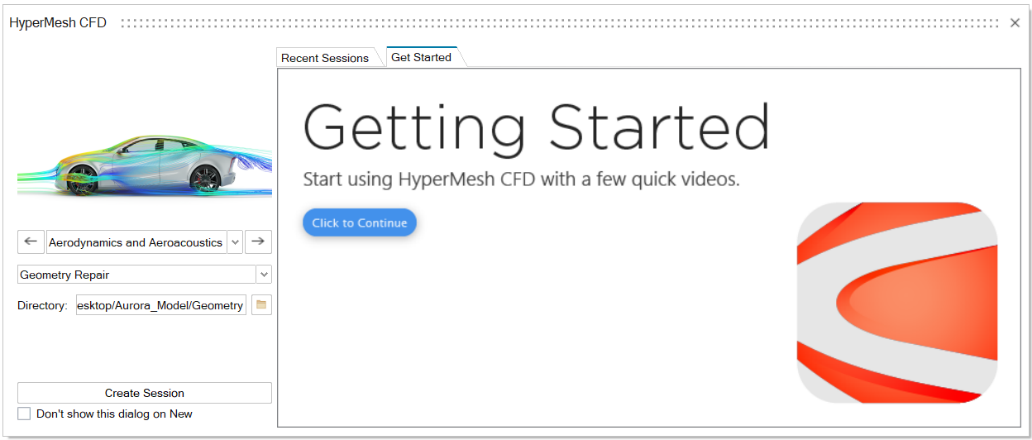 If HyperMesh CFD is already launched, you can create a new session by going to File → New, or by clicking the New Model icon in the Home ribbon.
Figure 3. 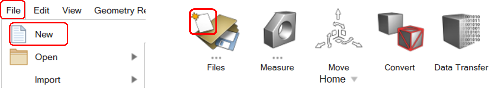 You can also change the Solution and Modelling Environment after the startup dialog:
- To change the solution, go to: .
Figure 4. 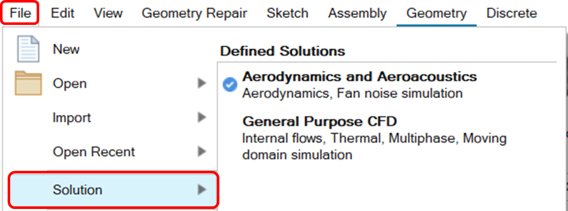
- To change the modelling environment use the modelling
environment switcher on the top of the HyperMesh CFD
window.
Figure 5. 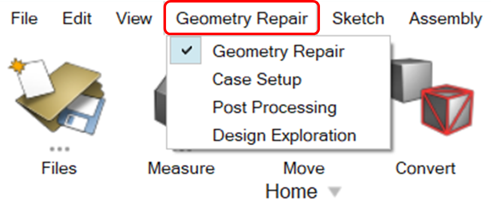
- To change the solution, go to: .
Import File (STL files)
-
Open a HyperMesh CFD session and go to and click on “Solver Deck”.
Figure 6. 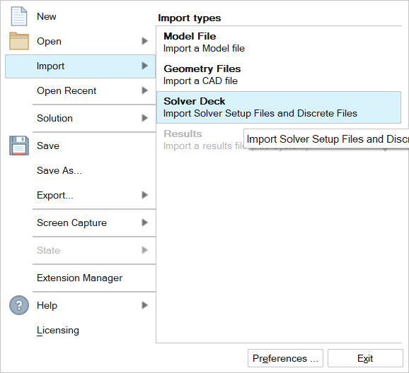
-
Navigate to Input Files folder, select all STL files and
click Open.
Figure 7. 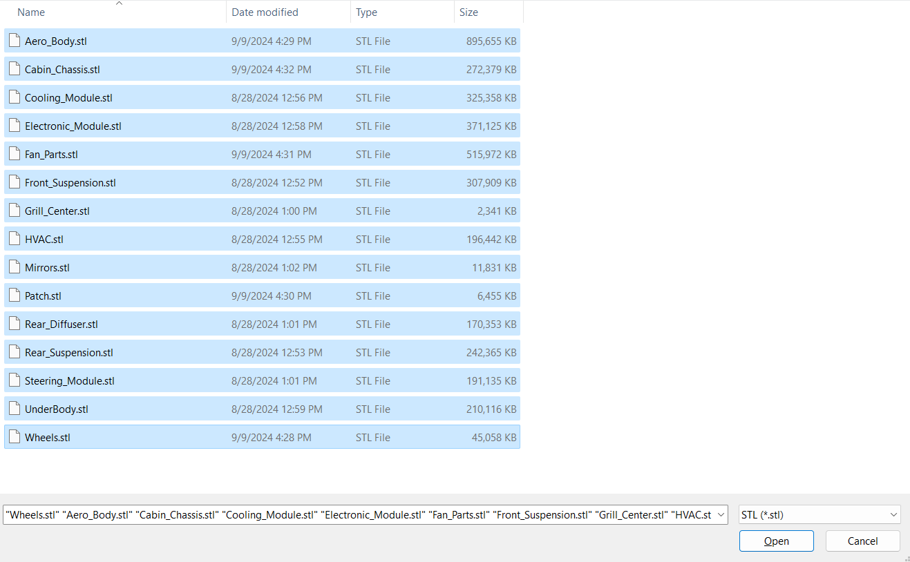
-
Keep default options and click Import.
Figure 8. 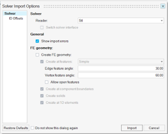
Navigate Through Parts
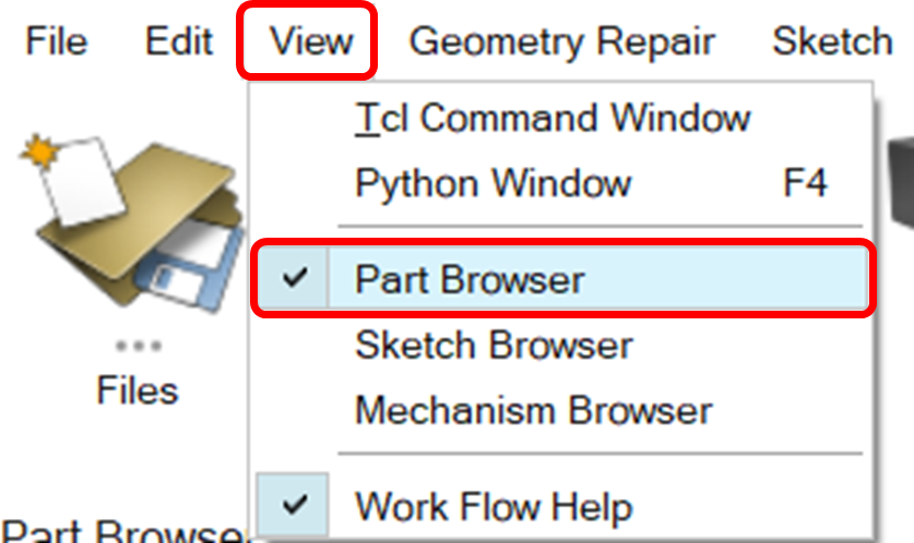
Part Browser
Visibility Settings
-
Right-click on an individual assembly/part icon in the browser to show/hide the
specific assembly/part.
Figure 10. 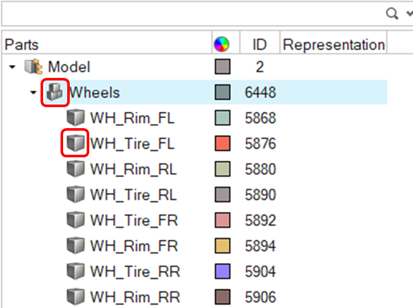
-
Use the Model icon to show/hide the entire model.
Figure 11. 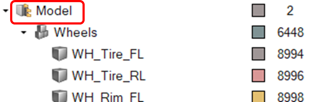
-
Right click on a part/assembly and choose any of the available options.
Figure 12. 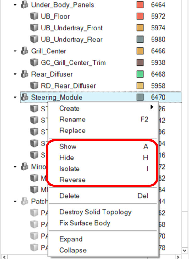
-
Select a part/assembly and press A to show, H to hide or I to isolate.
The previous tasks can also be done for multiple assemblies/parts at once.
Auto-Color Parts
You can automatically assign different colors to parts, making part visualization more convenient.
- Select the parts to automatically assign different colors or use CTRL+A to select all displayed parts.
-
On the Part Browser, left-click on any of the selected
parts color icon → click on the lightning bolt icon.
Figure 13. 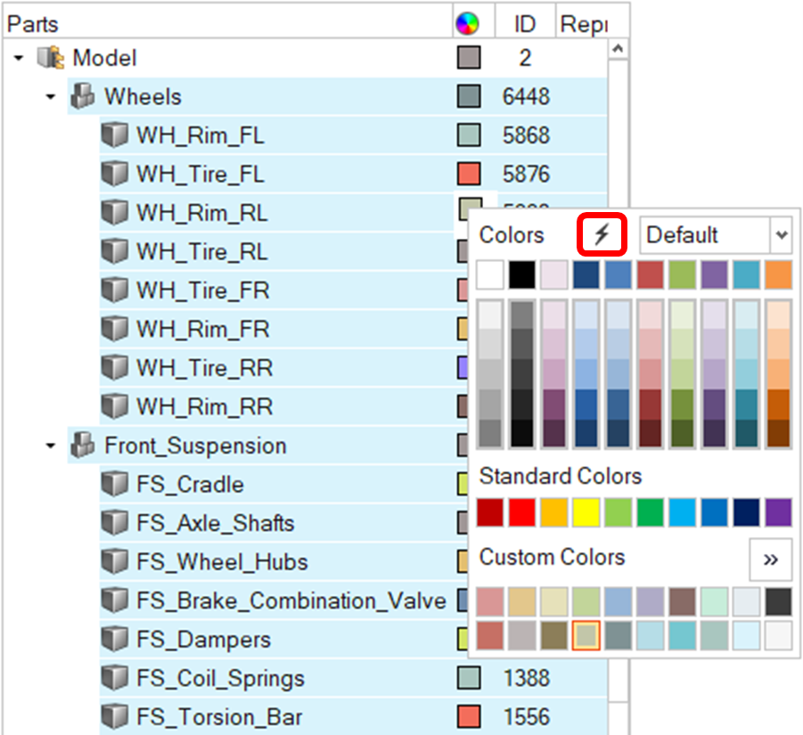
Part Management
Merge or Split parts
Merge/Split tool allows you to merge selected parts or split parts based on bodies.
- In the part browser, select Wheels assembly, then right click and select Isolate and hide Tires.
-
Merge rim parts into one part.
-
Select Merge option in the guidebar, then click
 Note: Change name if required after merge.
Figure 14. 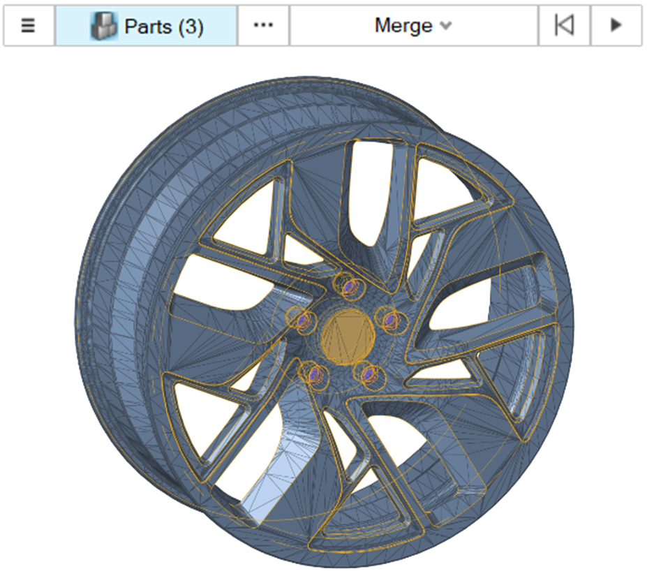
Figure 15. 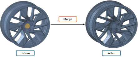
Similarly, you can merge other rim parts. -
Select Merge option in the guidebar, then click
Create New Assembly for Fan Parts
- Right click on empty space in browser then click Create Assembly.
- Right click on new part and Rename it Fan_Parts.
-
Select all fan parts from the part browser and drag them into the Fan_Parts
assembly.
Note: The fan parts can be renamed using FP at the start of their name. This is done to make organization better and part search easier.
Heat Exchanger Modelling
Create Boxes
Create boxes to represent heat exchanger core’s porous media region. Heat exchanger cores are modeled as boxes which are identified as Porous Media during Case Setup.
-
Select CM_HX1_Core part from the Part
Browser and isolate it.
Note: The box can be created by either navigating to: , or by going to: . In this case the latter is preferred because the heat exchangers are angled and the Simplify Region tool allows for easier and faster creation of a box.
- Go to: .
- Choose the CM_HX1_Core part.
-
Specify the settings as shown.
Figure 16. 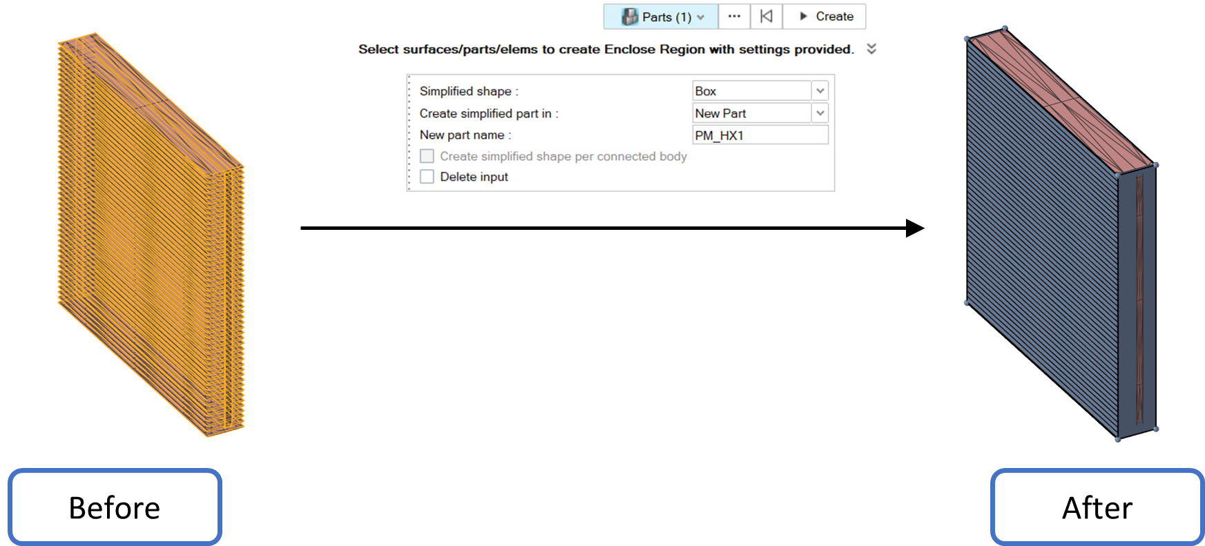 Note: Notice how the newly created box intersects the heat exchanger core, signaling that it completely covers it.
 - Repeat the same procedure for the rest of the heat exchanger cores.
Organize Porous Media Faces
- In the Part Browser, select PM_HX1_Walls part, then click Destroy Solid Topology.
- Right click on empty space in browser and then click Create part.
- Right click on the new part and rename it PM_HX1_Inlet.
- Select inlet surface, right click, then click Organize to part and select PM_HX1_Inlet.
- Repeat the same steps for the rest of the heat exchangers.
-
Create a new assembly for the porous media.
- Right click on empty space in browser and click Create Assembly.
- Right click on new part and Rename it Porous_Media.
- Select all PM parts from the part browser and drag them into the Porous_Media assembly.
Template Manager
Part Group Creation
The Template Manager uses part groups to execute specified operations.
-
Go to .
The Template Manager opens.
Figure 17. 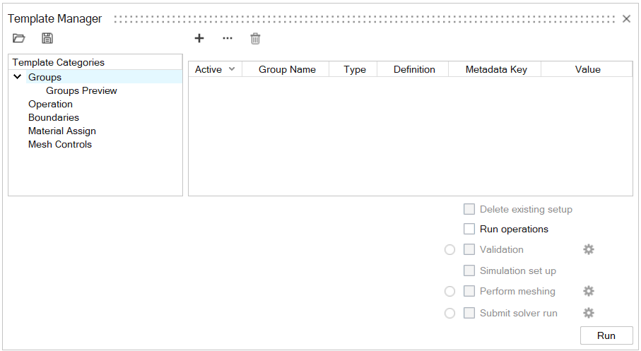
-
Note: Groups can be created by either clicking the plus signClick
 or the three dots
 .
.- Using the plus sign allows for the creation of groups containing multiple assemblies/parts.
- Using the three dots is useful for creating groups containing one assembly/part. Note that the create groups will bear the same name as the assembly specified.
, then . Select the Wheels assembly and click
Ok.
Figure 18. 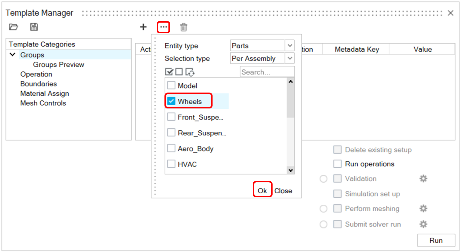 The created part group is named Wheels, the same as the selected assembly. The group can be renamed by clicking on the group name and entering a new.
Figure 19. 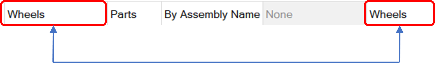
In the same way, the part groups for the Cabin_Chassis, Fan_Blades and Porous_Media assemblies can be created.
-
Click , then click on None under the Group
Name column.
- Name the group as Body.
- Specify Entity Type as Parts.
- Specify selection type as By Assembly.
- Click on None under the Value column.
- Enter the following assembly names: Aero_Body, Cabin_Chassis, Grill_Center, Rear_Diffuser, Mirrors, UnderBody, Patch.
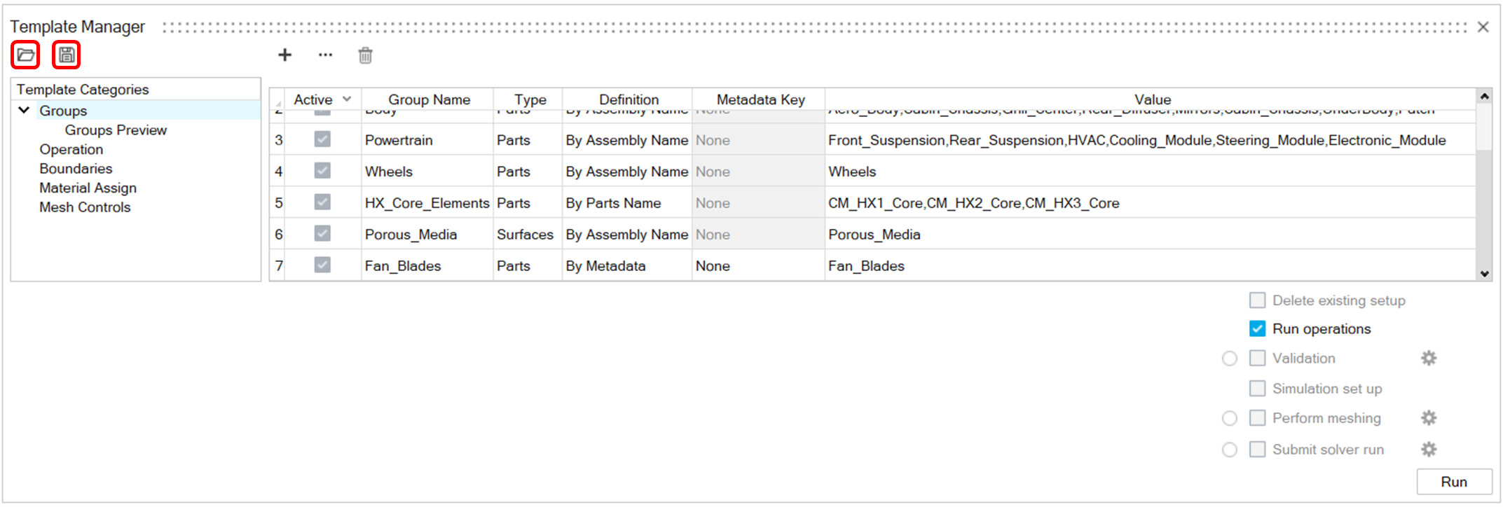
Figure 20.  The part groups that are needed for this tutorial are the following:
Table 1. Part Group Name Type Definition Assemblies Chassis Parts Per Assembly Name Cabin_Chassis Body Parts Per Assembly Name Aero_Body, Cabin_Chassis, Grill_Center,
Rear_Diffuser, Mirrors, UnderBody, Patch
Powertrain Parts Per Assembly Name Front_Suspension, Rear_Suspension, HVAC, Cooling_Module,Steering_Module, Electronic_Module Wheels Parts Per Assembly Name Wheels HX_Core_Elements Parts Per Parts Name CM_HX1_Core,CM_HX2_Core,
CM_HX3_Core
Porous_Media Surfaces Per Assembly Name Porous_Media Fan_Parts Parts Per Assembly Name Fan_Parts After defining the groups to be created, click on Run operations and then on Run to create them. Use the Groups Preview tab to see the generated groups.Figure 21. 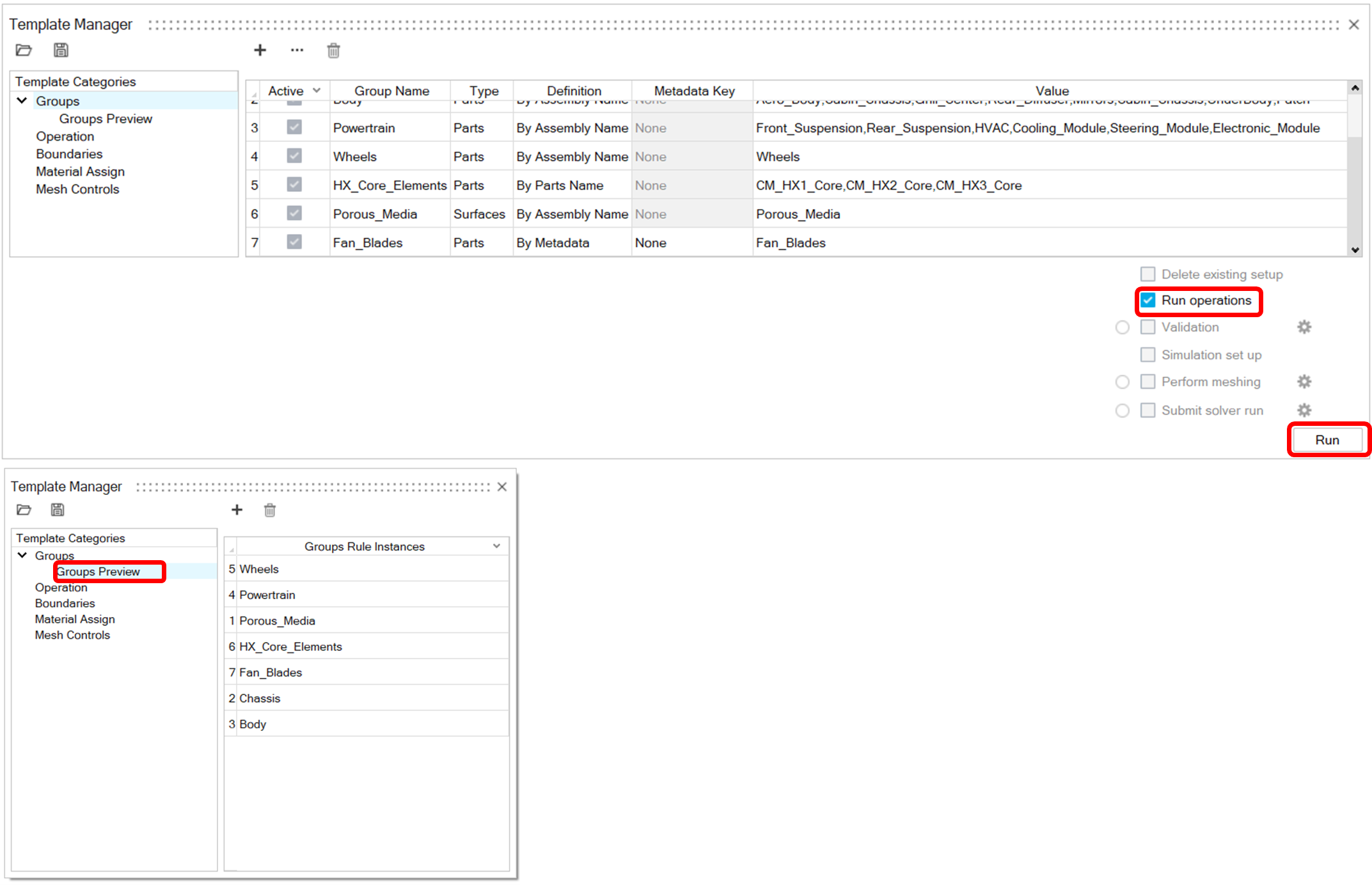
Delete HX_Core_Elements
- Click on the Operation tab.
-
Click the Add button.
-
Click on None under the Operation
column and from the list select Delete.
Figure 22. 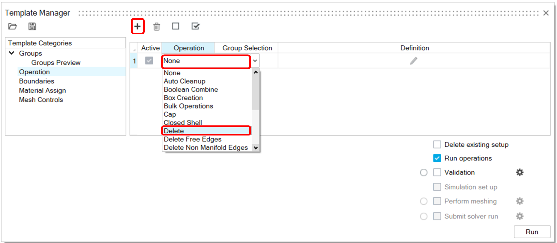
-
Click on None under the Group
Selection column and from the list select the
HX_Core_Elements group.
Figure 23. 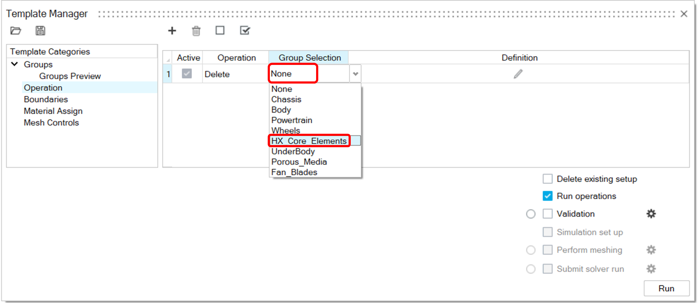
Wrap Wheels and Fix Normals
-
Click on the Add button.
- Click on None under the Operation column and from the list select Bulk Operations.
- Click on None under the Group Selection column and from the list select the Wheels group.
-
Click on
 . From the window that is displayed, select
CAD wrap parameters and Fix normal, click on the
. From the window that is displayed, select
CAD wrap parameters and Fix normal, click on the
 double arrows to expand the CAD wrap parameters settings and specify them as
shown below.
double arrows to expand the CAD wrap parameters settings and specify them as
shown below.
Figure 24. 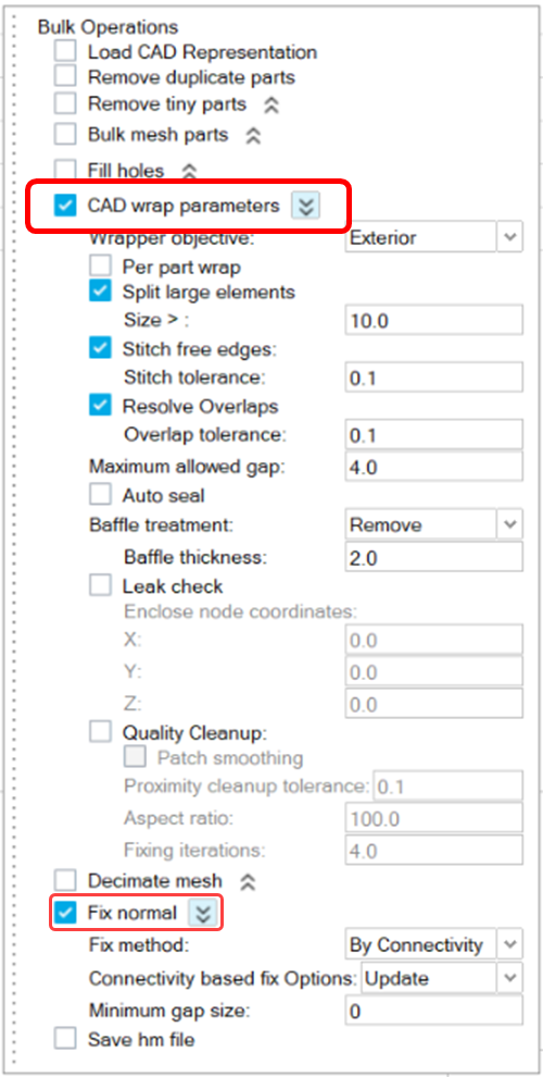
Cap Chassis
-
Click the Add button.
- Click on None under the Operation column and from the list select Bulk Operations.
- Click on None under the Group Selection column and from the list select the Chassis group.
-
Click on. From the window that is displayed select
Fill holes, click on the double arrows to
expand the Fill holes settings and specify them as shown
below.
Figure 25. 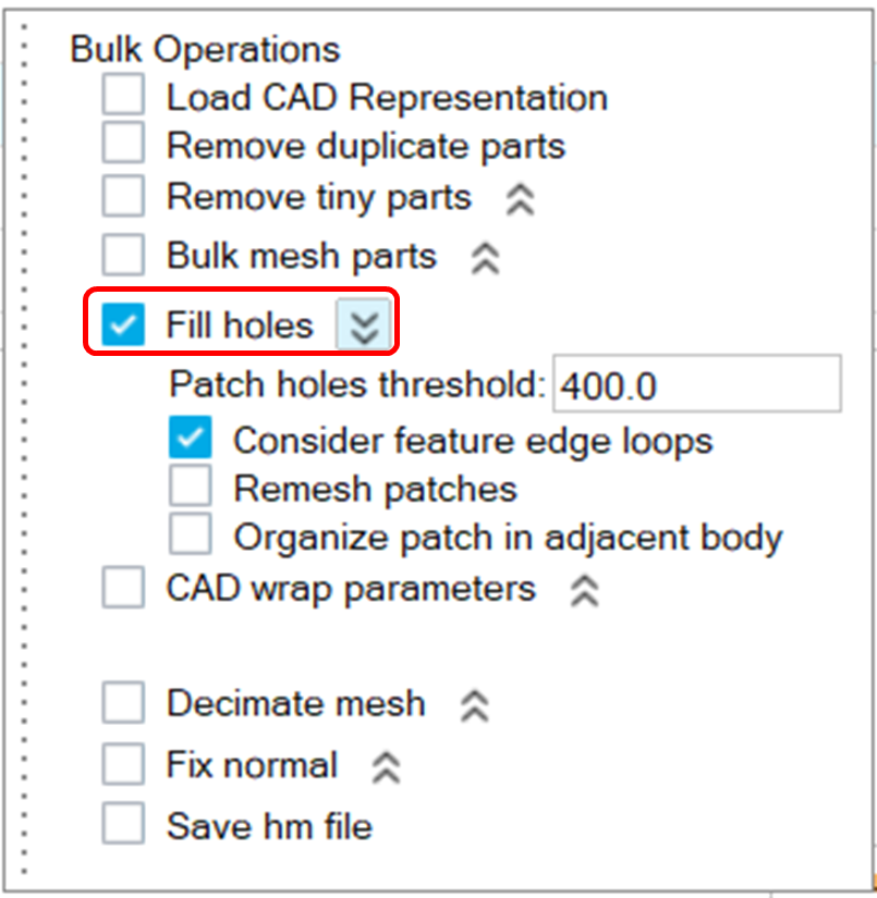
Wrap Body and Fix Normals
-
Click the Add button.
- Click on None under the Operation column and from the list select Bulk Operations.
- Click on None under the Group Selection column and from the list select the Body group.
-
Click on. From the window that is displayed select
CAD wrap parameters and Fix normal, click on the
double arrows to expand the Fill holes
settings and specify them as shown below.
Figure 26. 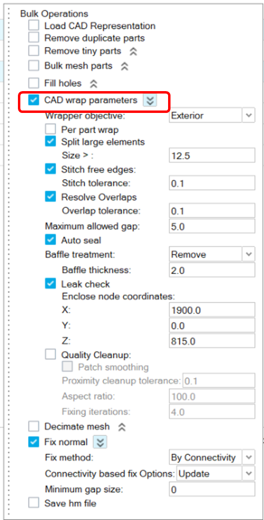
Delete Tiny Parts and Cap Powertrain
-
Click the Add button.
- Click on None under the Operation column and from the list select Bulk Operations.
- Click on None under the Group Selection column and from the list select the Powertrain group.
-
Click on. From the window that is displayed select
Remove tiny parts and Fill
holes, click on the double arrows to
expand each operation’s settings and specify them as shown below.
Figure 27. 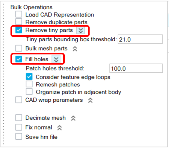
Wrap Powertrain and Fix Normals
-
Click the Add button.
- Click on None under the Operation column and from the list select Bulk Operations.
- Click on None under the Group Selection column and from the list select the Powertrain group.
-
Click on. From the window that is displayed select
CAD wrap parameters and Fix normal, click on the
double arrows to expand the settings and specify them as shown
below.
Figure 28. 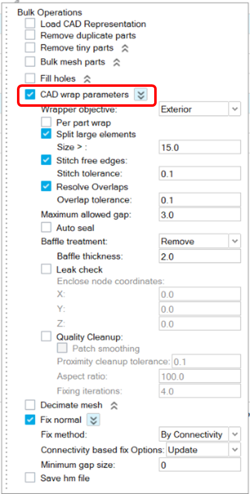
Wrap Fan Parts and Fix Normal
-
Click the Add button.
- Click on None under the Operation column and from the list select Bulk Operations.
- Click on None under the Group Selection column and from the list select the Fan_Parts group.
-
Click on. From the window that is displayed select
CAD wrap parameters and Fix normal, click on the
double arrows to expand the settings and specify them as shown
below.
Figure 29. 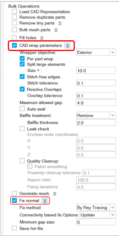
Tesselate Porous Media Surfaces
-
Click the Add button.
- Click on None under the Operation column and from the list select Tesselation.
- Click on None under the Group Selection column and from the list select the Porous_Media group.
-
Click on and specify the settings as shown below.
Figure 30. 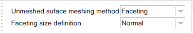
Run the Template
-
Make sure that all groups and operations are active.
Figure 31. 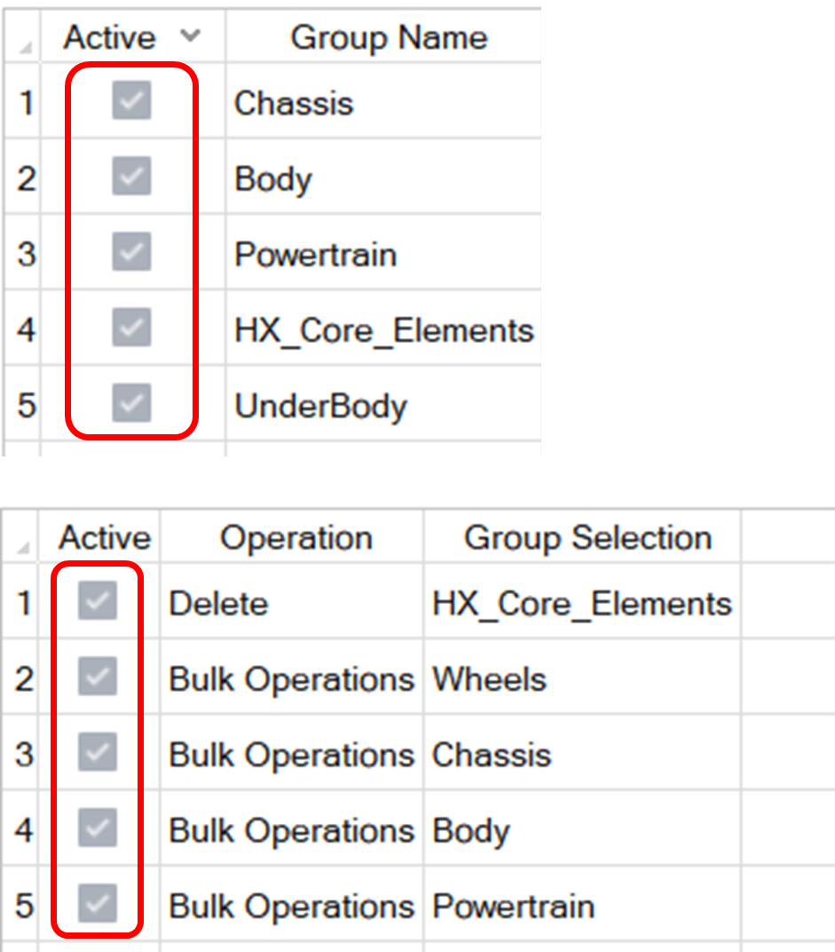 Note: Deactivating operations to run a smaller number of them is a useful tool to check if operations are working as expected.
 - Make sure that the model is in Mixed representation, so that the baffles will be deleted during wrapping.
-
Click on Run Operations and then on
Run.
Note: Due to the tessellation operation, the model will be in FeGeometry representation after the template has finished running.
Exporting and Importing the Template
-
To export the template, click on the Save button
 on the top of the window.
-
To import a template into the template manager, click on the
Open button
 on
the top of the window.
on
the top of the window.
Figure 32.