
HMCFD-T: 1010 Enclosure Workflow
Tutorial Level: Intermediate
Before you begin, copy the file(s) used in this
tutorial to your working directory.
Group the Solids to be Enclosed
- Open the PowerTrain_Model_Defeaturing.hm file.
- Make sure the entity selector in the modeling window is set to Parts.
-
While holding the Ctrl key,
select the solids depicted in the figure below.
Figure 1. 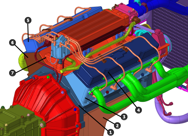
-
From the Assembly ribbon, click the Group tool.
Figure 2. 
-
Make sure that you have 7 parts selected by observing the number in parentheses
on the guide bar selector.
Figure 3. 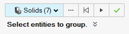
-
On the guide bar, click
 to execute the command and remain in the
tool.
to execute the command and remain in the
tool.
Figure 4. 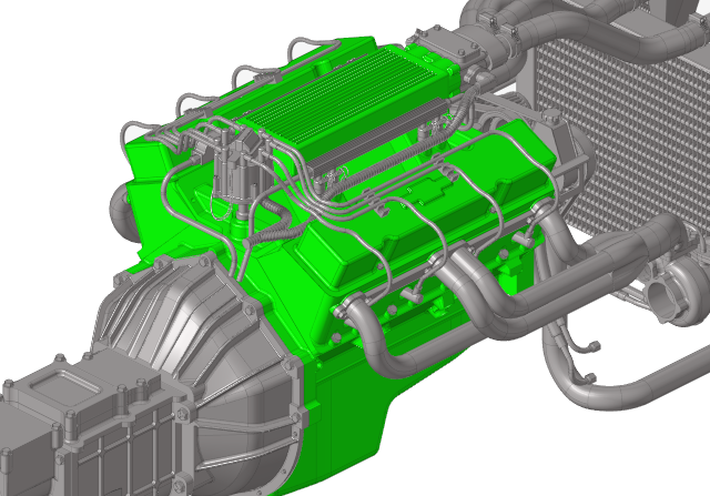
- In the Groups legend, rename the Parts Group to For_Wrapping.
-
Right-click For_Wrapping and select
Isolate.
This displays only the parts that will be enclosed.
-
On the guide bar, click
 to exit
the tool.
to exit
the tool.
- Save the model.
Convert CAD Geometry to an FE (Tessellated) Model
-
From the Home tools, click the Convert tool.
Figure 5. 
The Convert CAD to FE dialog opens. - Select FeGeometry as the type to convert to.
-
Ensure that Faceting is selected for the Unmeshed
surface meshing method and that the faceting size definition is set to
Normal.
Figure 6. 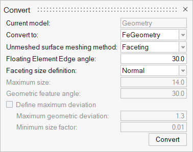
- Click Convert.
- Press Esc to exit the tool.
- Save the model.
Cap Holes and Other Openings
Small holes and other openings which only increase the mesh count and do not contribute to the simulation are capped/closed off before the enclosure of the geometry is done.
- Ensure that you have only the parts belonging to the "For_Wrapping" group displayed on the screen. If not, click the Group tool, right-click on For_Wrapping in the legend, and select Isolate.
-
From the Discrete ribbon, click the tool.
Figure 7. 
- Enter a value of 40 for the Maximum Width.
-
Select all surfaces on the screen using one of the following methods:
- Left-click and drag over the entire model.
- Press Ctrl + A.
Ensure that you have 2925 surfaces displayed on the guide bar's surface selector.Figure 8. 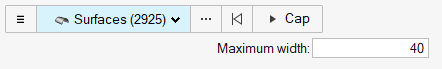
- Click Cap to begin the capping process.
- Change the guide bar selector from Surfaces to Nodes.
-
Select the four nodes shown in Figure 9.
Figure 9. 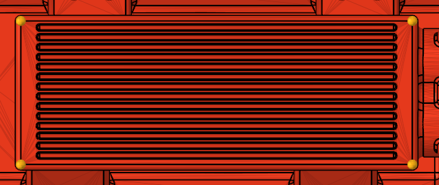
- Click Cap to begin the capping process.
-
Click the tool.
Figure 10. 
-
In the dialog, set the wrapping method to Tight Wrap,
enter the value of 20 for the Average element size, and
leave all other options as their default values.
Figure 11. 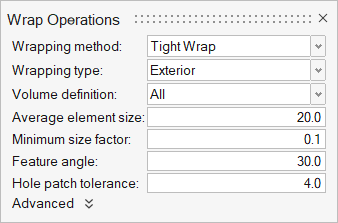
- Select all Parts on the screen.
- Click Run to execute the wrapping operation.
- Press Esc to exit the tool.
- Save the model.
Re-mesh Enclosed Results
-
From the Discrete ribbon, click the Remesh tool.
Figure 12. 
- Select all surfaces on the screen.
-
In the dialog, set the Average size to 20 and leave all
other options as their default values.
Figure 13. 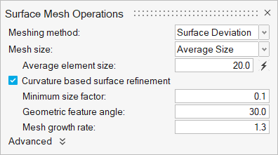
- Click Mesh on the guide bar to execute the re-mesh operation.
- Press Esc to exit the tool.
- Save the model.
Fix Enclosed Geometry
-
From the Discrete ribbon, click the Auto Repair
tool.
Figure 14. 
- Select all parts on the screen.
-
Click
 on the guide bar. Ensure
that Intersection cleanup is checked.
on the guide bar. Ensure
that Intersection cleanup is checked.
Figure 15. 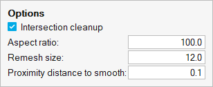
- Click Fix to initiate the repair of the wrapped surface model.
- Press Esc to exit the tool.
-
Save the model.
Figure 16. 