HMCFD-T: 1000 Basic Geometry Editing
Tutorial Level: Beginner
Before you begin, copy the file(s) used in this
tutorial to your working directory.
Validate the Geometry
- Open the Manifold_Model.hm file.
-
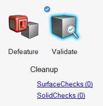
From the Geometry ribbon, click the Validate tool.
Figure 1. 
The Validate tool scans through the entire model, performs checks on the surfaces and solids, and flags any defects in the geometry, such as free edges, closed shells, intersections, duplicates, and slivers.The current model shows 13 surface related issues.Figure 2. 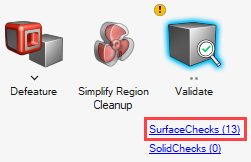
- Click SurfaceChecks to open the surface repair tool.
Fix Surfaces
-
In the SurfaceChecks legend, click Free edges (13) to
highlight all the free edges in the model.
Figure 3. 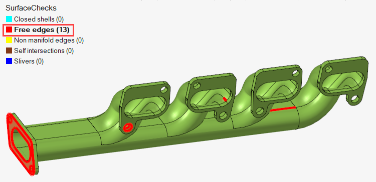
-
On the guide bar, enter a value of
2.0e-4 for the stitch tolerance and click
Stitch All.
Figure 4. 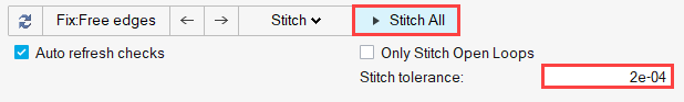
Observe that the number of free edges in the SurfaceChecks legend is reduced from 13 to 7. The remaining free edges are large holes which will be patched.
- On the guide bar, click on the drop-down arrow next to Stitch and select Patch Hole.
-
Click Patch All to patch up all the highlighted holes in
the geometry.
Observe that in SurfaceChecks legend you obtained a closed shell from the prior operations.
Figure 5. 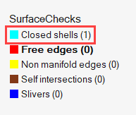
- Click Closed shells (1) in the SurfaceChecks legend and then select Create All on the guide bar.
- Press Esc to exit the tool.
-
Save the model.
The Surface geometry is now converted into a solid geometry and can be viewed in the Part Browser ().
Figure 6.
Extract the Fluid Domain
In this step, you will use the solid geometry to extract the internal fluid as a part, which you will then use for the simulation.
-
Click the Plug tool.
Figure 7. 
-
Click Find on the guide bar.
All the holes which can be plugged are highlighted.
Figure 8. 
-
Left-click any one of the manifold openings (Inlet or Outlets).
On selecting the opening, all the other manifold openings are closed, leaving behind the bolt holes on the flanges.
Figure 9. 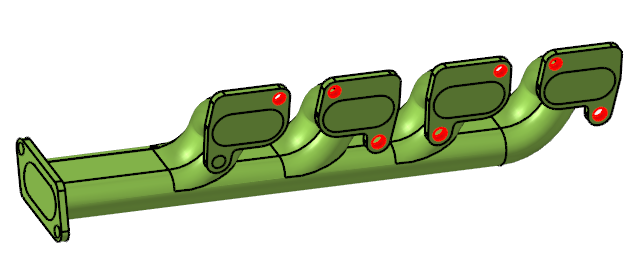
- Press Esc to exit the tool.
-
Open the Part Browser from the View menu if you have not
already.
You should see two SolidBody parts under the Body folder corresponding to the solid shell and the fluid.
-
Right-click on SolidBody_3_1 and select
Delete.
The Fluid geometry is displayed in the modeling window.
Figure 10. 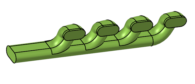
- Save the model.
Extrude Boundaries of the Fluid Domain
-
From the Drag/Spin tool group, click the
Drag tool.
Figure 11. 
- Select the individual ports to highlight them.
- Click on the individual ports to highlight them.
-
In the microdialog:
-
Disable Retain Shared Edges
 .
.
Figure 12. 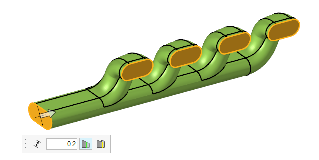
-
Disable Retain Shared Edges
- Press Esc to exit the tool.
- Save the model.
Defeature Faces
- Switch the entity selector in the modeling window to Surfaces.
-
Select all the surfaces shown in Figure 13 and
Figure 14.
The total number of surfaces should 7.
Figure 13. 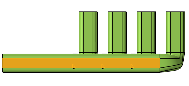
Figure 14. 
-
Right-click and select .
Observe that the edges of the smaller faces are now represented by dotted lines. These lines will not take part in the meshing process.
-
Repeat step 3 for the four surfaces shown in Figure 15 and
Figure 16
Figure 15. 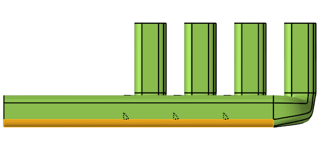
Figure 16. 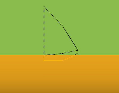
- Save the model.
Create an Interface
-
Click the Split tool.
Figure 17. 
-
From the secondary ribbon, click the Plane tool.
Figure 18. 
- On the guide bar, change the Target selector from Surfaces to Solids.
- Select the manifold.
- Click Tool on the guide bar.
-
Hover over the end of the inlet until the tool snaps to a point on the surface
boundary of the outlet, such as the Mid point.
Figure 19. 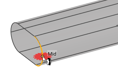
-
Enter 1,0,0 as values for the unit vectors x, y, and z
in the microdialog then press Enter.
Figure 20. 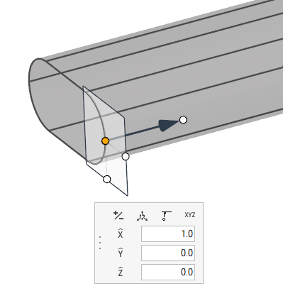
-
Click
 to open the Move
tool.
to open the Move
tool.
- Double-click on the Z-axis arrow to open its input dialog.
-
Enter a value of 0.5 and press Enter.
The tool shifts its position to the original outlet position.
Figure 21. 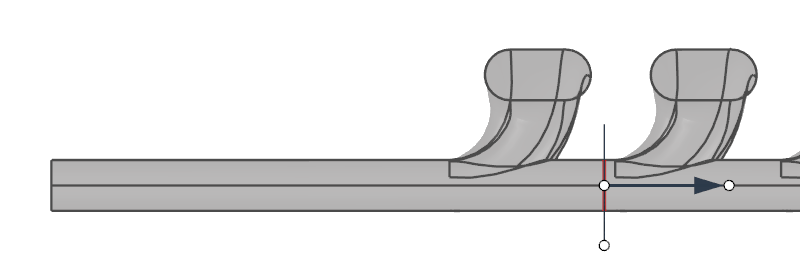
-
Click Split in the microdialog
to execute the split.
The two solids are now connected by a single interface.
- Click Target on the guide bar.
- Select the right-most solid.
-
Repeat steps 5-11 with a z-displacement value of
0.65.
You should now have three solids separated by two interfaces.
-
Click Target on the guide bar,
select the right-most solid, and repeat steps 5-11 with a z-displacement value
of 0.80.
You should have four solids separated by three interfaces as shown in Figure 22.
Figure 22. 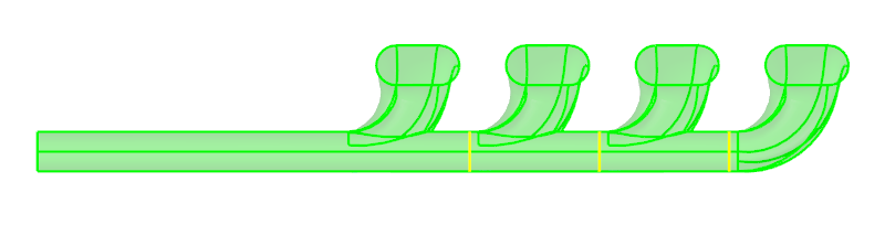
- Press Esc to exit the tool.
- Save the model.
Re-Validate the Geometry
-
Click the Validate
tool.
Figure 23.
-
Observe that a blue check mark appears on the top-left corner of the Validate
icon.
This indicates that the tool found no issues with the geometry model.
Figure 24.