HMCFD-T: 1030 Defeaturing
Tutorial Level: Intermediate
In this tutorial, you will look at some of the defeaturing tools available in HyperMesh CFD. You will use a transmission model to help explore the various options while cleaning up the geometry.
Before you begin, copy the file(s) used in this
tutorial to your working directory.
Defeature Small Bolts
-
From the Geometry ribbon, click the Defeature tool.
Figure 1. 
-
From the secondary ribbon, select the Small Features tool.
Figure 2. 
-
On the guide bar, click
 and set the size to 20.
This value describes the size limit up to which the software should detect a part.
and set the size to 20.
This value describes the size limit up to which the software should detect a part. -
Click Find.
The bolts less than 20mm are highlighted in red.
Figure 3. 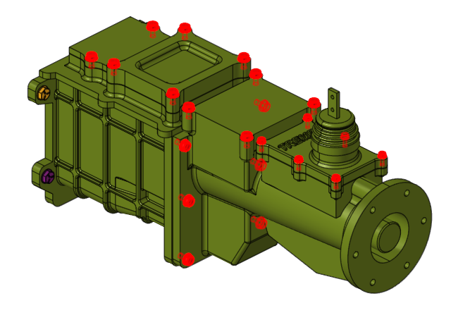
-
Click Remove All.
Some bolts that weren’t detected during the Find operation can be manually removed.
-
Select the four bolts shown below then click Remove All
again.
Figure 4. 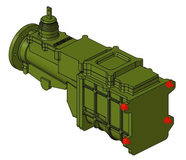
- Press Esc to exit the tool.
- Save the model.
Remove Logos from the Geometry
-
Select the Logos tool from the
Defeature secondary ribbon.
Figure 5. 
-
On the guide bar, click
Find.
The tool searches for any logos in the model.
Figure 6. 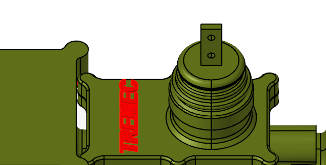
- Click Remove All.
- Press Esc to exit the tool.
- Save the model.
Defeature Fillets
-
Select the Fillets tool from
the Defeature secondary ribbon.
Figure 7. 
-
Select a continuous fillet loop, as shown in the figure below.
Figure 8. 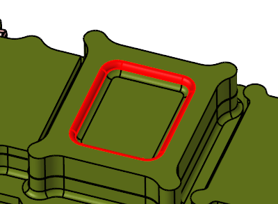
- Click Remove All on the guide bar to remove the fillet.
- Press Esc to exit the tool.
- Save the model.
Fill Out the Bolt Grooves
-
Select the Holes tool from the
Defeature secondary ribbon.
Figure 9. 
-
On the guide bar, click and enable Find cylindrical holes only.
-
Click Find.
All the holes in the geometry are highlighted.
Figure 10. 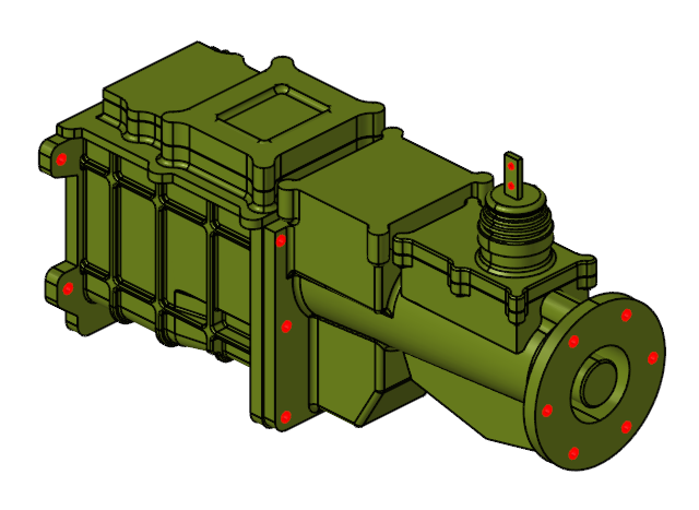
- Click Remove All.
- Press Esc to exit the tool.
- Save the model.
Perform a Batch Repair to Suppress Small Edges
-
Select the Batch tool from the
Defeature secondary ribbon.
Figure 11. 
-
On the guide bar, click and set the minimum size threshold to 3.0.
Figure 12. 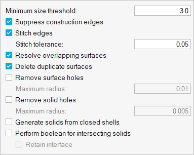
- Press Ctrl + A or left-click and drag across the geometry to select all the solid bodies.
-
Click Batch Repair to execute the batch process.
Observe that the suppressed edges are identified by dashed lines.
Figure 13. 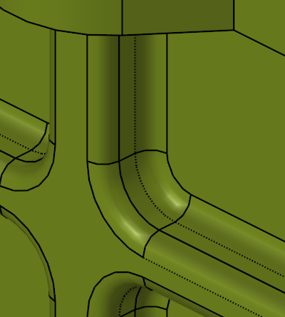
- Press Esc to exit the tool.
-
Save the model.
The geometry should now look that shown in the figure below.
Figure 14.