Use the Move tool to translate, rotate, and
position selected entities.
Certain types of entities, like assemblies, cannot be moved with the Move tool. Entities like pressures
cannot be moved because their position and orientation are determined by the entity to which they are applied.
From the Home tools, click the Move tool.
Figure 1.
In the external aero setup environment, you can also press
M or T.
In the general environment, the default move mode is set to
Interactive.
Optional: In the general environment, click
on the guide bar to define movement options.
In the general environment, select an entity
type using the guide bar selector.
Select entities and click
Move.
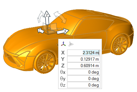
The Move tool is placed in the center of
selected entities.
Tip: Use the middle mouse button to confirm the selection and activate
the Move manipulator.
Click a graphical manipulator, and then do one of the following:
Drag the entity or graphical
manipulator to translate or rotate entities in the selected direction(s).
Enter a precise value in the microdialog and
press Enter.
Press Ctrl and select two locations to align
an axis to a vector or three locations to align an axis to a plane
normal.
Note: The Ctrl + click action
is valid only for translation and rotation manipulators.
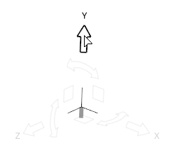
To
Do This
Translate along an axis
Click the X, Y, or Z arrow.Figure 2.
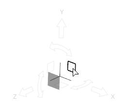
Translate along a plane
Click the XY, XZ, or YX plane square.Figure 3.
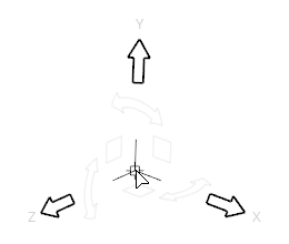
Translate freely in 3D space
Click and drag from the origin of the Move tool.Figure 4.
Tip: Use the icons in the microdialog to align the tool to a
part or the global axes.
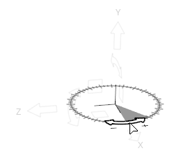
Rotate around an axis
Click a curved arrow.Figure 5.
Rotate freely
Click at the tip
of the X, Y, or Z arrow and drag. In the external
aero setup environment, an axis line appears and the
unresolved rotation is prompted on release.Figure 6.
Figure 7.
Tip: Use snap points to align entities by
clicking-and-dragging a snap point on one entity
to the snap point on a second entity.
Tip: When translating entities between two locations,
the distance between the picked locations is automatically calculated in the
increment field (Inc.) and can be modified if needed.Figure 8.
Microdialog Options
When clicking the Move tool origin:
Align the Move tool its default orientation and
position:
Click once to reset its orientation to match the global
coordinate system, or local system if one is assigned.
Click twice to also reset its position to the centroid of your
selection, or the local system origin if one is assigned.
Align the Move tool along an edge or face. If
the Move tool is being repositioned
(highlighted orange), clicking this button will force the Move tool to be aligned automatically as you drag it
around the model.
Select and assign a local coordinate system to the Move tool. After a new system is assigned, the
Move tool automatically repositions to its
origin.
Note: Currently, the Move tool only supports assigning rectangular
coordinate systems.
Tip: When a local system is assigned to the
Move tool, the system button is shown with a tick
mark , indicating that the manipulator is now in local
system mode. Click this button again to change the assigned system or reset it
to go back to global system mode.
When clicking a translation or rotation arrow:
Orient the selected direction using the Vector
tool.
Inc.
Use the buttons to apply an incremental translation
or rotation in the selected direction.
Tip: When using the Vector tool to define an orientation between two snaps,
the Inc. (increment) field is also automatically populated with the
corresponding distance.
Keyboard Shortcuts
Table 1.
To do this
Press
Quickly align the manipulator to two or three
locations


 on the guide bar to define movement options.
 at the tip
of the X, Y, or Z arrow and drag. In the external
aero setup environment, an axis line appears and the
unresolved rotation is prompted on release.
at the tip
of the X, Y, or Z arrow and drag. In the external
aero setup environment, an axis line appears and the
unresolved rotation is prompted on release.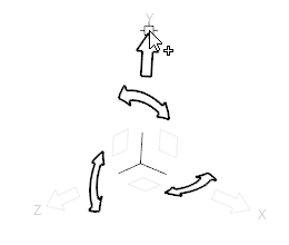


 , indicating that the manipulator is now in local
system mode. Click this button again to change the assigned system or reset it
to go back to global system mode.
, indicating that the manipulator is now in local
system mode. Click this button again to change the assigned system or reset it
to go back to global system mode.
 buttons to apply an incremental translation
or rotation in the selected direction.
buttons to apply an incremental translation
or rotation in the selected direction.