Boundary Conditions
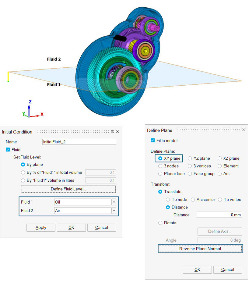
Initial Condition
Analysis ribbon > Boundary Conditions > Initial Condition
Initial Condition is used to define and create the fluid (liquid and gas) regions inside the container. This is useful when the CAD or FE model does not have a separate body for the fluids. The fluid option will be displayed based on single-phase (one fluid) and multiphase (two fluids) options in the Solution panel.
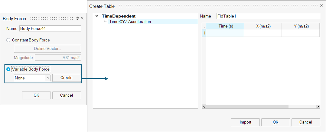
Body Force
Analysis ribbon > Boundary Conditions > Body Force

Domain
Analysis ribbon > Boundary Conditions > Domain
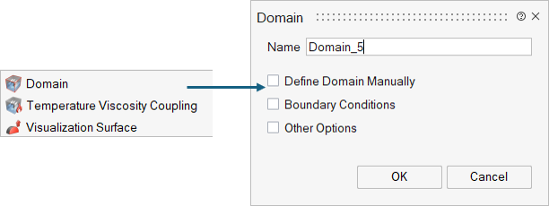
- Define Domain Manually
- If the simulation has an open boundary, or if there are periodic boundary conditions associated with the domain, it is necessary to manually prescribe the size of the domain (bounding box). In this case the padding around the particles should be set to 3*dx.
- Boundary Conditions
- These domain parameters are used to define the boundary conditions at minimum and maximum boundary. Boundary options supported are Periodic and Simple Outlet (default).
- Other Options
- A free text box where additional parameters can be specified.
Motion
Analysis ribbon > Boundary Conditions > Motion
Wall boundary particles can be moved during a simulation with a prescribed motion, where in principal a motion for a specific phase/ body is defined and applied within a given time frame.
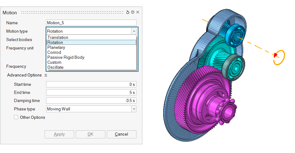
Planetary gears motion is normally accompanied by a Rotation motion for the carrier. Conrod motion (definition of a piston and conrod mechanism) is normally accompanied by a Rotation motion for the crankshaft.
Oscillatory motion is defined for motion of an object from its mean position.
Passive Rigid Body motion defines a 6-DOF rigid body freely interacting with the fluid. Constraints, forces, and damping are available for each translation and rotation component.
For the most complex motions a Custom motion can be defined. This allows the import of a time history file from Multi Body Dynamics solver to define any kind of arbitrary motion.
MotionSolve and InspireMotion export this file natively. Other solvers may be able to produce the file required.
Inlet
Analysis ribbon > Boundary Conditions > Inlet
- Stencil spawn surface
- Extension (optional)
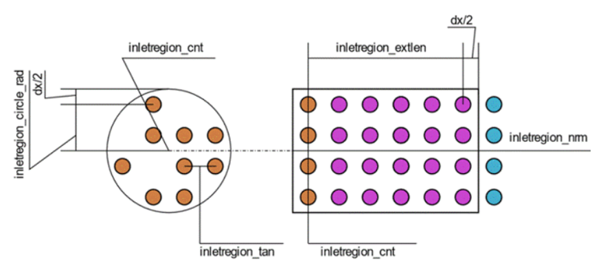
- Inlet Stencil
- Inlet stencil is created for the inlet region which behaves as a source of particles and will be exported as a .txt file for the inlet region containing the x-, y-, and z- coordinates of the particles which are to be inserted into the domain.
- The spacing of the stencil must match the dx value used for the rest of
the simulation.
Figure 7. 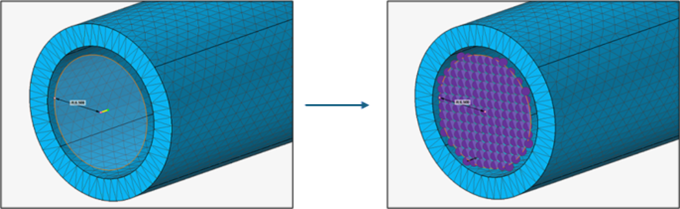 Important: When the stencil is generated, it will be placed in a model named InletRegionsProbes.gda. The stencils must remain in the model. Otherwise, they will not be exported correctly. This model is always exported to the .cfg, regardless of whether it is displayed during export.Check the stencil against the wall particles to ensure there are no overlaps or penetrations. The figure below shows an example of a misaligned stencil and conduit.
Figure 8. 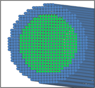
As the fluid particles leave the extension, the distance between fluid-fluid particles and fluid-wall particles are not similar. This results in a pressure rise on the side where fluid particles are closer to the wall. Depending on the severity of the misalignment, this may result in undesired secondary flows.
- Inlet Extension
- The extension imposes the inlet velocity and ensures the distance
between different spawn layers remaining at dx. As a result, extension
is an important component of the Inlet region.
The extension covers up to half dx, further in each direction than the definitions given in the *.cfg to ensure all spawned Inlet region particles are covered. The fluid particles within the extension have the same velocity as the inlet region. It is important that the spawn area is not disturbed by other fluid particles. The extension only applies to the fluid phase specified for that specific inlet region.
While possible, disabling the extension is generally not recommended unless it is guaranteed that the spawn area will remain undisturbed during the active interval of the Inlet region. Moving Inlet regions always requires an extension to function properly.
Care must be taken to ensure that any change in profile or shape of the conduit downstream of the Inlet region does not conflict with the extension. If there is a conflict, the extension will push the particles through the conduit wall. It is not guaranteed that the particles will be out of the wall at the end of the extension.
Define Inlet in SimLab
- Name: Inlet region name.
- Material: Specifies the phase of the fluid spawned by the inlet region.
- Inlet Shape: Specifies the shape of the inlet region.
- Inlet Type: Specifies the type of the inlet region. Inflow can be defined via Velocity, Mass or Volume flow and can be constant and time dependent.
- Start Time/ End Time: Specifies the start and finish times which define the window where the Inlet region is active.
- Ramp up Time/ Ramp down Time: This parameter specifies a time window for the acceleration and deceleration of the fluid. At the start time, the flow will ramp up from zero to the specified value over this time. If ramp down is specified, the velocity will ramp back down to zero prior to the end time. This minimizes pressure fluctuations and instabilities caused by instantaneous changes in velocity.
- Prefilled: To be activated if fluid particles coinciding with stencil positions are present when inlet region becomes active.
- Moving body motion to follow: If active, user has to select moving body that would be followed by inlet region.
- Other Options: A free text box where additional parameters can be specified.
- Inlet Temperature Treatment
- After having the Heat Transfer Coefficient (HTC) calculations available in
nanoFluidX, it becomes necessary to apply
simple temperature boundary conditions to inlet regions. Inlet fluid
temperatures may be specified for each inlet region via the other options
text box in the Inlet Regions dialog menu, without the
need to define a separate fluid phase. Specified temperature will stay
constant within the inlet region and inlet extensions.Note:
- The temperature value remains constant throughout the simulation and does not offer any ramp or time-series input. When discharging fluids of different temperatures into a bulk, please choose a suitable initial bulk temperature to avoid extreme differences in temperature.
- Constant temperature is enforced within the extensions if the extension is active. This means that if inletregion_extpre and/or inletregion_extpst are set to true, the temperature control within the extension is maintained before and/or after the inlet region’s active particle spawn interval.
Outlet
Analysis ribbon > Boundary Conditions > Outlet
Outlet regions use a combination of removal and extension regions to allow particles of any phase to be removed from anywhere within the computational domain. Every particle that enters an outlet region will be removed from the simulation permanently.
- Spherical
- Cylindrical
- Cuboidal
Cylindrical and cuboidal outlet regions can optionally have an extension region, like inlet region extensions, which can define either velocity or acceleration within its volume.
An extension is an extended region in the opposite direction of the outlet region's normal where a constant particle velocity or acceleration in the normal direction is enforced. When used without extensions, outlet regions act as pseudo zero pressure and zero stress boundaries with no back flow. Although it must be noted that since the particles are missing neighbors (incomplete support), these conditions are not strictly met, hence pseudo.
When used with an extension and provided that the extension is well populated, the behavior depends on the type of extension.
Spherical outlet region cannot have an extension and acts as a simple particle sink.
Define Outlet in SimLab
- Name: Outlet region name.
- Outlet Shape: Specifies the shape of the outlet region.
- Extension Type: Specifies the type of the outlet extension type:
- Velocity - When using the velocity extension type, the extension sets the normal component of particle velocity to the specified value. The particle velocity is free to evolve in directions perpendicular to the Outlet regions normal directions. The particles immediately outside of the extension will see this as some form of constant velocity outlet boundary. This is a loose form of boundary condition and the velocity felt by the particles immediately outside of the extension is not exactly equal to the Outlet region velocity. The pressure immediately outside the extension will adjust itself to support the flow through the extension. Applying zero velocity in velocity type extension will result in a clogged Outlet region.
- Acceleration - When using acceleration extension type, the extension sets the normal component of particle acceleration to the specified value. The particle acceleration is free to evolve in directions perpendicular to the Outlet regions normal direction. For particles immediately outside of the extension, the particles in the extension represent a form of outlet boundary with constant acceleration. The pressure immediately outside the extension will adjust itself to support the flow through the extension.
- Start Time / End Time: Specifies the start and finish times which define the window where the Outlet region is active.
- Ramp Up / Down Time: This parameter specifies a time window for the acceleration and deceleration of the fluid. At the start time, the flow will ramp up from zero to the specified value over this time. If ramp down is specified, the velocity will ramp back down to zero prior to the end time. This minimizes pressure fluctuations and instabilities caused by instantaneous changes in velocity.
- Extendent Length (dx): The length of the extended region in terms of particle spacing.
- Material: Outlet regions can be set to apply only to specific phases. For example, removing one fluid only. It is also possible to specify wall phases. In this situation, an opening can be created in the wall by the Outlet region.
- Other Options: A free text box where additional parameters can be specified.
Regions
Define any number of regions to alter/prescribe velocity, acceleration, porous media or temperature.
- Velocity
- Analysis > Boundary Conditions > Regions > Velocity
- Create Impose Velocity Region in SimLab
-
- Name: Impose velocity region name.
- Region Type: Specifies the type of the impose velocity region.
- Velocity Type:
- Constant - Imposed velocity inside the region.
- Time Series - Defines variable velocity inside the imposed region.
- Parabolic velocity: Enables a parabolic velocity profile when cylindrical imposed velocity regions are used.
- Cylinder cap: Controls adding hemispherical caps on the cylinder bases (resulting in a pill-shape geometry). The caps are added to both sides of the cylinder.
- Start Time/ End Time: Specifies the start and finish times which define the window where the impose region is active.
- Damping Time: This parameter specifies a time window for the acceleration of the fluid. At the start time the velocity will ramp up from zero to the specified value over this time. This minimizes pressure fluctuations and instabilities caused by instantaneous changes in velocity.
- Advanced Options:
- Mode - Defines the mode of the impose region, are the specified values added or set inside the impose region. Options are SET, ADD.
- Constraint - Defines the constraint of the impose region, are the specified values strictly or loosely imposed in the region. Options are: LOOSE, STRICT.
- Moving body motion to follow - Impose regions can follow a MOVINGWALL phase with a predefined motion.
- Impose Acceleration
- Analysis > Boundary Conditions > Regions > Acceleration
- Create Impose Acceleration Region in SimLab
-
- Name: Impose acceleration region name.
- Region Type: Specifies the type of the impose acceleration region.
- Acceleration Type:
- Constant - Imposed acceleration inside the region.
- Time Series - Defines variable acceleration inside the imposed region.
- Cylinder cap: Controls adding hemispherical caps on the cylinder bases (resulting in a pill-shape geometry). The caps are added to both sides of the cylinder.
- Start Time/ End Time: Specifies the start and finish times which define the window where the impose region is active.
- Damping Time: Damping time of the prescribed acceleration.
- Advanced Options:
- Mode - Defines the mode of the impose region, are the specified values added or set inside the impose region. Options are SET, ADD.
- Constraint - Defines the constraint of the impose region, are the specified values strictly or loosely imposed in the region. Options are: LOOSE, STRICT.
- Moving body motion to follow - Impose regions can follow a MOVINGWALL phase with a predefined motion.
- Other Options: A free text box where additional parameters can be specified.
- Impose Porous
- Analysis > Boundary Conditions > Regions > Porous
- Create Impose Porous region in SimLab
-
- Name: Impose porous region name.
- Region Type: Specifies the type of porous region.
- Start Time/ End Time: Specifies the start and finish times which define the window where the impose region is active.
- Advanced Options: Moving body motion to follow - Impose regions can follow a MOVINGWALL phase with a predefined motion.
- Other Options: A free text box where additional parameters can be specified.
- Impose Temperature
- Analysis > Boundary conditions > Regions > Temperature
- Create Impose Temperature Region in SimLab
-
- Name: Impose temperature region name.
- Region Type: Specifies the type of the impose temperature region.
- Temperature Type:
- Constant - Imposed temperature inside the region.
- Time Series - Defines variable temperature inside the imposed region.
- Cylinder cap: Controls adding hemispherical caps on the cylinder bases (resulting in a pill-shape geometry). The caps are added to both sides of the cylinder.
- Start Time/ End Time: Specifies the start and finish times which define the window where the impose region is active.
- Damping Time: Damping time of the prescribed temperature.
- Advanced Options:
- Mode - Defines the mode of the impose region, are the specified values added or set inside the impose region. Options are SET, ADD.
- Moving body motion to follow - Impose regions can follow a MOVINGWALL phase with a predefined motion.
- Other Options: A free text box where additional parameters can be specified.
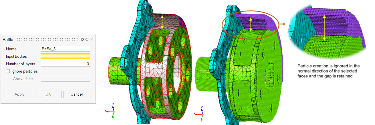
Baffle
Analysis > Boundary conditions > Baffle