Use the Altair Bushing Model with MotionSolve
This section provides information about using the Altair Bushing Model, also known as AutoBushFD, with MotionSolve.
The information is also applicable for other solver packages including:
- MATLABTM
- ADAMSTM
- SIMPACKTM
Principles of Usage
The following principles are in play when using the Altair Bushing Model with MotionSolve. While the specific elements you add to your model for a bushing depend on the host simulation tool, the principles of usage remain the same.
- The bushing model acts between two bodies, for example, between a suspension control arm and sub-frame. These bodies are referred to as Body-I and Body-J at a point fixed in Body-I (on a marker on Body-I using MotionSolve).
- Inputs to the simulation model are the displacement and velocity, both translational and rotational, of Body-I relative to Body-J in a specified coordinate system fixed in Body-J (on a marker on Body-J using MotionSolve).
- Outputs from the simulation model are the forces and torques on Body-I in the specified coordinate system fixed in Body-J.
- The simulation model requires the host simulation tool to integrate the model’s internal states associated with bushing force formulation.
- Altair Bushing Model in a MotionSolve Model
- The Altair Bushing Model is complex and relies
on a number of atomic solver elements to represent the individual effects
described earlier in this guide. The figure below illustrates these elements
and the data flow between them as they exist in a single Altair Bushing Model within a MotionSolve model.
Figure 1. 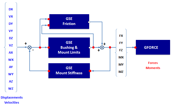
- Components of a Bushing Model
- The following sections describe the components shown above in more detail:
- Data Blocks
- The blocks in the simulation model include:
Table 1. Block Description GSE-Friction (Control_StateEqn) Computes the friction moment. The friction acts in response to rotational motions of the I-Body relative to the J-Body. GSE-Bushing (Control_StateEqn) Computes the bushing forces and moments and the time derivatives of states associated with the bushing forces and moments. This modeling entity also includes the forces and moments due to the bushing reaching the limits of its travel. This may include material contact between the I-Body and J-Body. GSE-MountLimits (Control_StateEqn) Computes the local structural deflection and rate of change of deflection given the sum of the friction, bushing, and limit forces and moments acting between the I-Body and J-Body. GFO FORCE (Force_Vector_TwoBody) Applies the net bushing forces and moments to the I-Body and J-Body. For examples of blocks in the .gbs file, see: Bushing Property File. Bushing design data is passed in through a combination of files and solver REFERENCE_ARRAYs and String objects.
- Inputs
- Regardless of the bushing model used with it, the Altair Bushing Model requires twelve (12)
inputs, which are listed for you in the following table. These
inputs are the displacements and velocities between the two
bodies measured at the location where the bushing acts.
[A] = angle dimension, [L] = length, [T] = time
Table 2. Input Units Description MotionSolve Function U(1) [L] X-deflection DX(i,rm,rm) U(2) [L][T-1] X-deflection-rate VX(i,rm,rm,rm) U(3) [L] Y-deflection DY(i,rm,rm) U(4) [L][T-1] Y-deflection-rate VY(i,rm,rm,rm) U(5) [L] Z-deflection DZ(i,rm,rm) U(6) [L][T-1] Z-deflection-rate VZ(i,rm,rm,rm) U(7) [A] Angular-deflection-X AX(i,rm,) U(8) [A][T-1] Angular-deflection-rate-X WX(i,rm,rm) U(9) [A] Angular-deflection-Y AY(i,rm,) U(10) [A] Angular-deflection-rate-Y WY(i,rm,rm) U(11) [A] Angular-deflection-Z AZ(i,rm,) U(12) [A] Angular-deflection-rate-Z WZ(i,rm,rm) - States
- The Altair Bushing Model uses internal states for modeling the following: dynamics inside of the bushing; structural deflection of mount bodies (Mount Stiffness; and friction slip (bristle) states. For rubber bushings these states model the rubber’s hysteretic, frequency-dependent and amplitude-dependent behavior. For hydromounts, these states model the rubber’s behavior in addition to the mass and flow of the internal fluid. For more information about bushing models, see: Theory and Formulations.
- Outputs
- As listed in the table below, the Altair Bushing Model has six (6) outputs,
three orthogonal forces, and three orthogonal moments acting on
the I-body. Equal and opposite forces and moments that obey
Newton’s Third Law are automatically applied on the
J-body.
[F] = force, [L] = length
Table 3. Output Units Description Function Y(1) [F] X direction Force on the I-Body FX (i, rm, rm) Y(2) [F] Y direction Force on the I-Body FY (i, rm, rm) Y(3) [F] Z direction Force on the I-Body FZ (i, rm, rm) Y(4) [F][L] Moment on the I-Body about the X axis TX (i, rm, rm) Y(5) [F][L] Moment on the I-Body about the Y axis TY (i, rm, rm) Y(6) [F][L] Moment on the I-Body about the Z axis TZ (i, rm, rm) - Parameters
- Prior to running an analysis, you have to define the parameters
governing the behavior of the bushing, and you have to select a
bushing property file. During the analysis the parameters do not
vary. All of the parameters that you can define are listed in
the table below. Note: All of these are optional except PROPERTY_FILE.
[A] = angle dimension, [F] = force, [L] = length, [T] = time
Table 4. Parameter Type Units Entity Description PROPERTY_FILE String NA GSE-Bushing The name and path of the .gbs that specifies the stiffness and damping data for the bushing. OFFSET_TRA Array: 3 real values [L] GSE-Bushing Translational displacement offsets for the bushing. OFFSET_ROT Array: 3 real values [A] GSE-Bushing Rotational displacement offsets for the bushing. PRELOAD_TRA Array: 3 real values [F] GSE-Bushing Force offsets for the bushing. PRELOAD_ROT Array: 3 real values [F][L] GSE-Bushing Torque offsets for the bushing. SCALE_DISP Array: 3 real values > 0 None GSE-Bushing Scales the {x, y, z} translational displacement inputs to the bushing. SCALE_RDISP Array: 3 real values > 0 None GSE-Bushing Scales the {rx, ry, rz} rotational displacement inputs to the bushing. SCALE_FORCE Array: 3 real values > 0 None GSE-Bushing Scales the bushing force {fx, fy, fz} outputs. SCALE_TORQUE Array: 3 real values > 0 None GSE-Bushing Scales the bushing torque {tx, ty, tz} outputs. LOCAL_STIFFNESS_ACT Array: 6 int values None Mount Switches the local stiffness: ON=1, OFF=0 for the X, Y, Z, RX, RY, RZ directions. For example {1,0,0,0,0,0} turns local stiffness on in the X direction, while all other directions are off (rigid). LOCAL_STIFFNESS_TRA Array: 3 real values ≥ 0 [F][L] Mount Combined local translational stiffness of I-Body and J-Body in the X, Y, Z directions. LOCAL_STIFFNESS_ROT Array: 3 real values ≥ 0 [F][L] Mount Combined rotational stiffness of I-Body and J-Body in the X, Y, Z directions. LOCAL_DAMPING_TRA Array: 3 real values ≥ 0 [F][T][L-1] Mount Combined local translational damping of the I-Body and J-Body in the X, Y, Z directions. LOCAL_DAMPING_ROT Array: 3 real values ≥ 0 [F][L][T][A]-1 Mount Combined local rotational damping of the I-Body and J-Body about the X,Y,Z directions. LOCAL_STIFNESS_FLAG Enumeration: always_on
always_off
rigidbody_only
No Units Mount Switches local stiffness on and off: always_on = stiffness is active.
always_off = stiffness is inactive.
rigidbody_only=stiffness is active when the I-Body and J-Body are both rigid-bodies.