
Part Shape Prediction
Use this tool to redesign the part boundary based on feedback from nesting analyses to improve design sustainability.
- Prepare and run a feasability analysis. See Feasibility Setup and Simulation and Feasibility Analysis.
- Prepare and run a blank nesting analysis. See Blank Nesting Analysis.
-
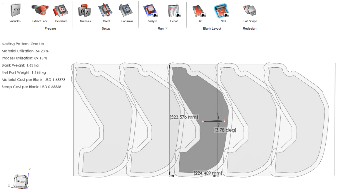
Evaluate the nest analysis for overlapping parts, as shown below:
-
Right-click a nested shape you would like to adjust in design, then select
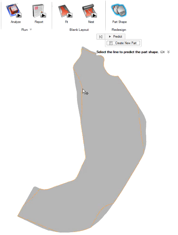
Extract nested blank.
The nested blank appears in the object browser.
-
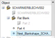
Click the Predict Part Shape tool.

-
Select the shape where you would like to predict the part shape.
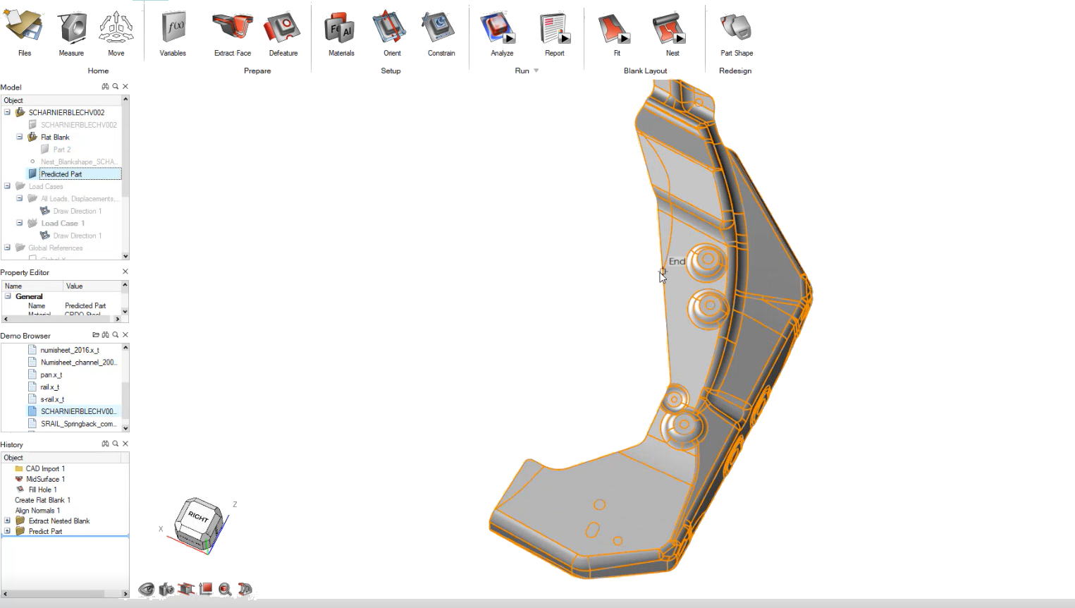
The predicted part shape traceline appears in the model.
 Note: Optionally, turn on Create new part if you would like the predicted part shape to show up as a new part in the object browser.
 -
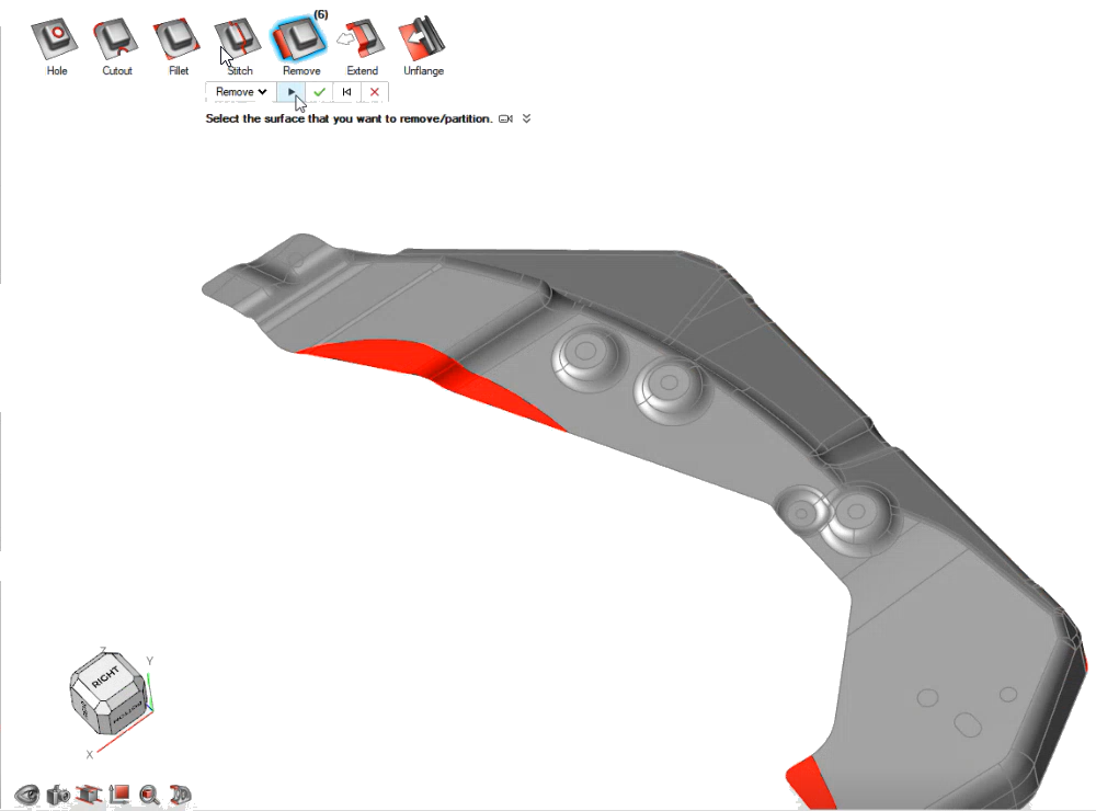
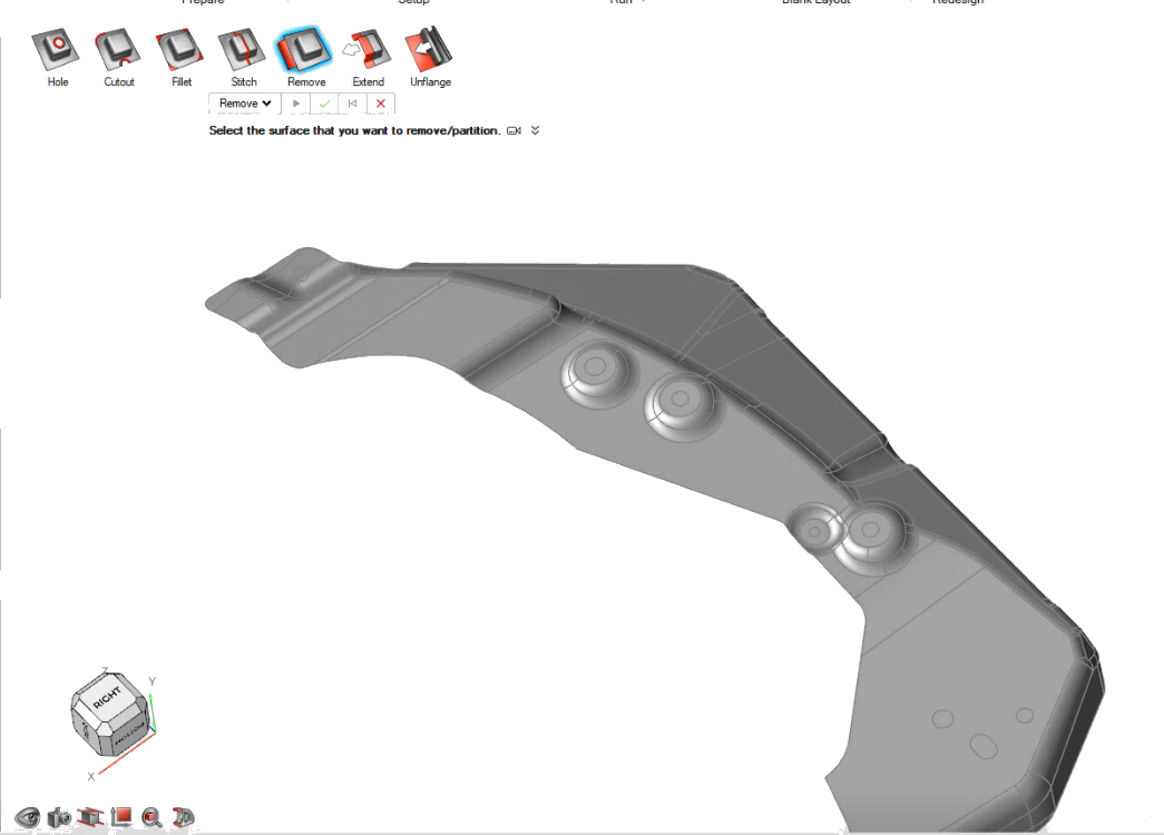
Based on the results of the part shape prediction, you can use the
Defeature toolset or the Geometry ribbon to adjust
your part shape to the predicted shape. For example, you can use the
Defeature tool to remove anything outside of the
part's predicted shape, or the Extend tool from Geometry
to extend the part to reach the part's best predicted boundary.
The images below show a simple Defeature using the Remove subtool.
- Rerun the feasability analysis. If you are not satisfied with the part shape prediction, you can readjust the design using the Defeature toolset or the Geometry ribbon, then run the feasibility analysis again.